This thread has been locked.

If you have a related question, please click the "Ask a related question" button in the top right corner. The newly created question will be automatically linked to this question.

TPS28226: TPS28226 not working correctly at a frequency of 22-30 Hz's

Part Number: TPS28226

Hi

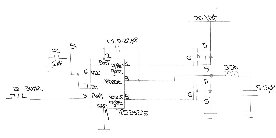
I have just built a Half H-bridge circuit using the TPS28226 with 2 n-type devices and have followed a similar design to the data sheet. But wish to use the output into a low frequency resonant circuit being 22Hz.

But the device does not perform correctly at this frequency. The fitted coil in the centre point of the bridge is 3,3 henry,  which is followed by a 8.5uF capacitor to give a resonant  frequency around 30 hz's. But the device does not function correctly and eventually malfunctions drawing excessive current.

I changed the device  and series capacitor to 47nf and the device act as you would expect at this higher frequency of 200-400hz region.

Question-1     Can the device be used at lower frequency around 22-30hz region ?

At the higher frequency level I changed the DC F.E.T Voltage to 10 Volts and damaged another device. When I looked at the TPS waveform on a a scope the resonant Voltage was good up to 32V which is what is probably damaging the device via the phase pin. Can this pin be protected from higher Voltages ?

I will download a copy of Tina and post my circuit layout over the weekend.

Any help will be greatly appreciated !!

Thanks Dave

  • Hello David,

    Thank you for your interest in driver products from Texas Instruments. I am an application engineer with TI and will work to help resolve your issues in the design.

    The first detail that I want to mention, at the low operating frequencies confirm that the high side bootstrap bias supply (BOOT to PHASE) voltage is maintained during the driver high side on time. Can you provide the component values of the VDD and bootstrap capacitors? Also is there any gate to source resistance on the high side MOSFET? The TPS28226 driver can function at low frequencies, but the bootstrap capacitor value needs to be adequate to maintain the high side bias.

    Since your application is a resonant load on the driver, it will help to see waveforms showing the PWM input, Phase voltage, and current going into the inductor. In many resonant type applications, it is desireable to have some dead time from the high side and low side switch to allow for the voltage transition between actively driving the power devices.

    Can you provide a schematic, and some waveforms to enable me to make more detailed suggestions?

    Richard

  • Hi Richard

    Thank you for your support. The bootstrap capacitors are 0.22uF caps connected between pins 2 & 8 of the TPS device. Please see the below schematic. Apologies for the hand drawing.

    The gate pins connects directly to the devices as shown below. The main FETs are IRF520N.

    Regards Dave

  • Hello David,
    Thank you for the schematic. For the very low operating frequencies the boot capacitor needs to be sized to maintain the boot strap voltage over the switching cycle.
    Since the quiescent current is not shown separate for the boot strap supply, the below is based on the assumption that it is 1/2 of the total current of 500uA.
    Size the boot capacitor by:
    Qtotal=Qg +Iboot/Fsw; Qtotal=25nC + 250uA/22Hz=11.39uC.
    For ripple of 0.5V: Cboot=Qtotal/deltaVboot = 11.39uC/0.5V=22.8uF.

    This is likely a very conservative (large) value for the boot capacitance, but it is much larger than the 0.22uF you have now.
    Try a significantly larger boot capacitor of 4.7uF to start. and size the VDD cap at 10x which will be 47uF.

    Confirm if larger boot and VDD capacitance resolves the operation issues.

    Richard Herring
  • Hi Richard

    Just a quick summary on the 22 Hz's testing.

    I tried several different sizes of capacitor and design changes. Although using the correct size capacitors improved the design. The pk-pk output voltage from the bridge could not be made bigger than 8V pk-pk. The circuit would also only work correctly at resonance and stopped functioning if the frequency was slightly changed.

    In the end I used a standard half bridge being driven indirectly from a controller due to time constraints. This functioned correctly, although I would have rather used the driver circuit.

    Thankyou for the support anyhow

    Regards Dave

  • Dave,
    Thank you for considering the TPS28226 for your circuit design. Thank you for confirming that you were able to achieve a workable solution, although the TPS28226 operation was not able to be resolved.
    Without seeing waveforms, I can't say exactly what the issues may be working over frequencies not at resonance.
    But at this low frequency operation, I am not sure a driver with 14ns dead time was the optimum solution. TI has an extensive portfolio of drivers with different features. I expect that there is a driver solution that would have worked well in your design.

    Regards,
    Richard Herring