Part Number: TPS65130EVM-063
Hello,
I have used the TPS65130 to create a +/- 5.5V rail from a 5V input. I was curious about improving the ripple on the negative output.
I am attaching my two scope shots.
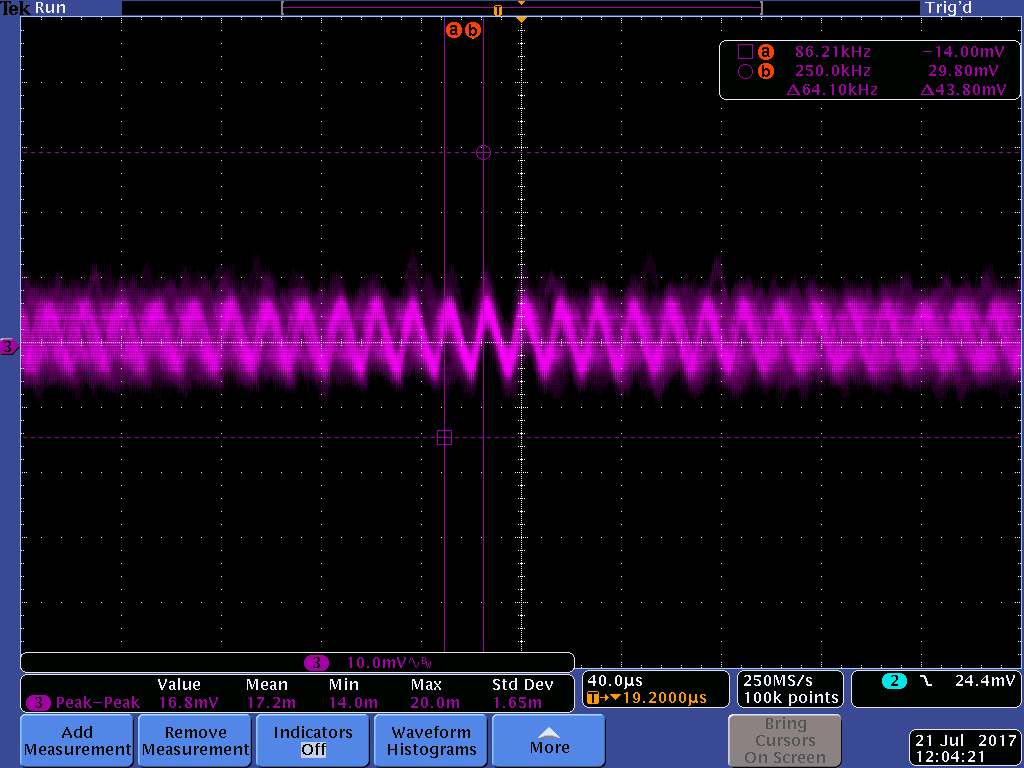
TEK00003 is the negative rail measured across the output caps (This ripple is 90mV, would like to get to 45mV)
TEK00004 is the positive rail measured across the output caps (This ripple is within specification)
I took the stock EVM and swapped out R3 = 576k and R5 = 750k. I did not modify anything else.
Do you have suggestions on improving this?
Thanks,
Jason Haedt
TEK00003
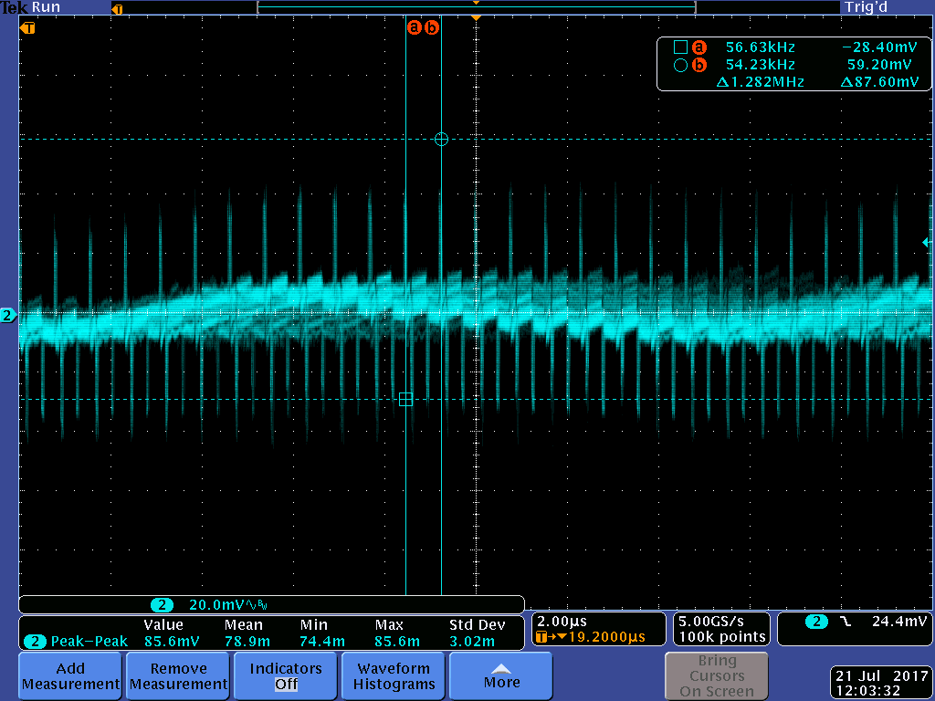
TEK000004