This thread has been locked.

If you have a related question, please click the "Ask a related question" button in the top right corner. The newly created question will be automatically linked to this question.

LP8758-E0: About start-up time

Part Number: LP8758-E0

Hi,

Could you tell me about caluculating start-up time of LP8758-E0.

I understand that total start-up time is the following "Soft start"period + "slew rate controlled"period.

"Soft start" period is typ 110uF. (written in datashet of P.11)

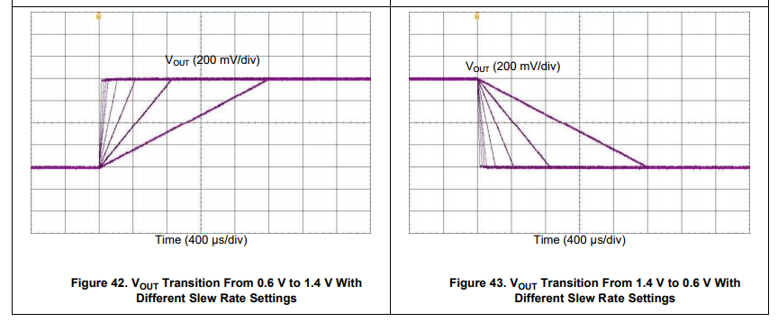
"slew-rate controlled" period is (Vout - 0.225V) ÷ (setting value of slew rate) .

As a result, max and min of start-up time are calculated considering the accuracy of slew rate(±15%), is it correct?

Could you give me advice if it is wrong?

Best Regards,

Yuto Sakai

  • Sakai-san,

    Thank you for posting your question on the LP8758-E0 in the e2e forum. Your thread has been assigned to the expert within TI, who will reply to your question as soon as possible and attempt to answer this question.

    Please keep in mind that many Europeans take holiday in the middle of summer and the response may be a little slower than usual.
  • Sakai-san,

    I also looked at the LP8758-E0 datasheet and believe your understanding is correct.

    (Vout - 0.225V) ÷ (setting value of slew rate)  is a good equation, but I will re-write it in more generic terms:

    Let us call soft-start time tSS, the slew-rate controlled time tSRC, the final output voltage Vout,new and the original output voltage Vout,old.

    tSRC = (Vout,new - Vout,old) ÷ (setting value of slew rate) 

    You can verify this equation by plugging in numbers and referring to Figure 42:

    • tSRC,[111]max = (1 + 0.15)*(1.4V - 0.6V)/(0.47mV/us) = 1957us, accounting for +15% allowed by max value you referenced on page 11.

    The ramp time for the longest value is just under 2000us in Figure 42, so the equation works.

    • tSRC,[110] = (1.4V - 0.6V)/(0.94mV/us) = 851us, using typical slew rate value for setting 110b of 0.94mV/us

    The ramp time for the 2nd longest value is just over 800us in Figure 42, so the equation works again. 

    You are trying to calculate the total ramp time shown in Figure 9 for when the output voltage starts at GND (0V) and ramps all the way to the final output voltage without stopping. Let us call this tRAMP and say we are transitioning all the way from GND to Vout = 1.8V with no stopping.

    tRAMP = tSS + tSRC, where tSRC,[111]max = (1 + 0.15)*(1.8V - 0.225V)/(0.47mV/us) = 3854us

    tRAMP = 110us + 3854us = 3964us < 4ms

    Assuming your output capacitance, COUT_TOTAL = 44uF and there is no load, then this should be a fairly accurate estimate.

    Since COUT_TOTAL can be modified in your design, it is best to measure tSS on your PCB and then add this to the calculated tSRC value.

    There are many factors involved, and they are listed in Note (2) on Page 11 of the datasheet:

    Specified by design without testing. The slew-rate can be limited by the current limit (forward or negative current limit), output capacitance, and load current.


    You should be able to say your design is acceptable based on the available data and your calculations, but it would be wise to factor in some margin for error. And of course, your final design needs to be tested across all operating conditions (load, temperature, etc) in the actual system.

  • Hi Brian-san,

    Thank you for your kind surpport.
    I confirmed the above contents.

    Best Regards,
    Yuto Sakai
  • Sakai-san,
    Thank you for confirming!