This thread has been locked.

If you have a related question, please click the "Ask a related question" button in the top right corner. The newly created question will be automatically linked to this question.

TPS1H100-Q1: ON/OFF time for TPS1H100-Q1

Part Number: TPS1H100-Q1


I would like to confirm the operation of thermal shutdown.

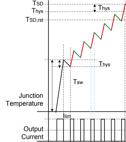
I understood the point of OFF (chip temperature = Tsw) and the point of ON at first (chip temperature = Tsw - Thys) at Figure 37.

But I don't know ON time and OFF time after first "ON" by TSD.

Could you please teach the ON/OFF time?

Best regards,

Atsushi Yamauchi

  • Hello Atsushi,

    I understand the confusion here, thank you for posting the question.

    In the image below, there are highlighted red segments. In these areas, the device is on and limiting the output current. I have added in the blue dotted lines to show the correlation between the red segments (device is on) to the output current at that time. The red lines show an increase in temperature of the device.

    The temperature of the device increases quick enough to trigger the Tsw threshold and disable the output. The green segments show when the device is disabled and the temperature of the device decreases.

    There reason there are multiple spikes for the "Output Current" waveform is because the rate at which the junction temperature increases is triggering the Tsw threshold multiple times.

    Best,

    Nick

  • Dear Nick-san,

    Thank you for your quick response.

    I understood the mechanism.

    I have questions.

    How much is the time of red segments and green segments?

    (When does the operation change from "ON" to "OFF" and from "OFF" to "ON" after second round?)

    Best regards,

    Atsushi Yamauchi

  • Hey Atsushi,

    How long it takes the device to cool down by THYS (The green segments) is affected by external system-level thermal considerations.

    Some examples would be:

    • the ambient temperature of the system
    • the thermal conduction of the PCB and surround components
    • airflow of the system

    I'm going to have to look deeper into the timing for the device temperature rising (red segments), I'll update when I get more information.

    Best,

    Nick

  • Hey Atsushi,

    Thank you for being patient.

    There are two thermal measurements, at different locations, that are taken within the device (in the datasheet, these are Tdmos and Tlogic in section 8.3.4.5). When the devices heats up rapidly (the red segments) the two thermal measurements will have different values for a short period of time. If the difference between the measurements is greater than the Tsw threshold (see below) then the output is disabled.

    Tdmos - Tlogic > Tsw

    The amount of time it takes for the Tsw threshold to be tripped depends on the thermal propagation properties of both the device and the PCB.

    Best,
    Nick