This thread has been locked.

If you have a related question, please click the "Ask a related question" button in the top right corner. The newly created question will be automatically linked to this question.

TPS62143: TPS62143 dies in field for unknown reason

Part Number: TPS62143

Hi,

We are using the TPS62143 in an RFID product of ours and the DC/DC converter seems to die for no apparent reason.

We are in contact with Mike Farley at TI and so far no root cause was identified. Only a few units so far were affected by the issue.

So far we were not able to see any issues with the supply to the board (12V) and the unit itself was succesfully UL certified. For protection we have transorbs but the issue doies not seem to come from external spikes. The circuit connected to the converter consumes 900mA max. Any more than that is only possible by external shorts of the provided RS485 interface as well as other gross issues in combination.

Based on that the circuit should not be able to overload the TPS62143. We sent a damaged IC for analysis to an external lab and it showed some blistering on the output (at least we assume it is the output FET).

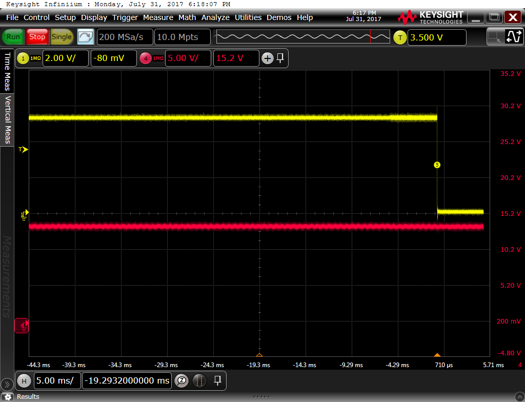
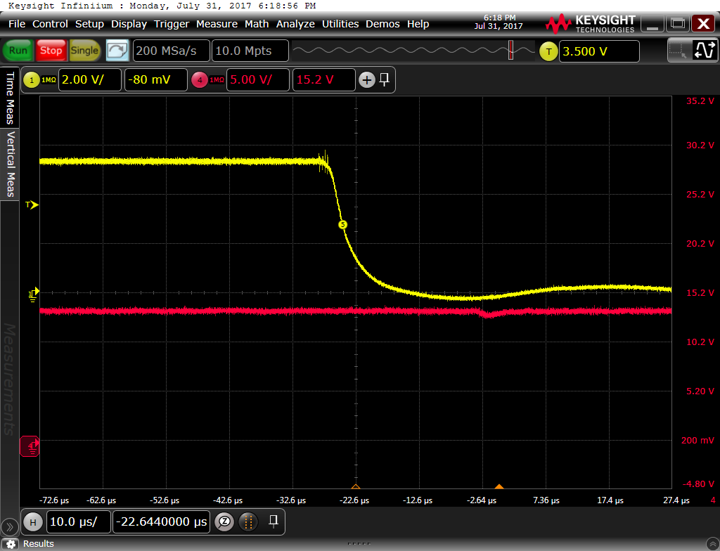
Monitoring the output voltage of the TPS62143 it seems stable at 5.25V (we use the DEF pin for higher output voltage). However, we managed to get a single unit to die in our lab by stressing it - LED blinking and sound playing whilst reading an RFID card.

Based on that I wanted to ask if a voltage spike on the output of the TPS62143 could kill the IC and what sort of amplitude such a spike would need to have (so far we did not see any).

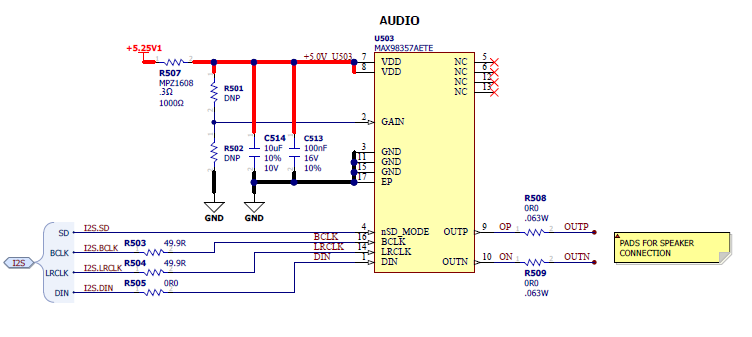
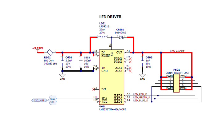
In addition I wanted to ask if the inductance of the speaker could cause a problem with the loop stability of the regulator. The supply circuit as well as the speaker driver and LED driver schematics are attached.

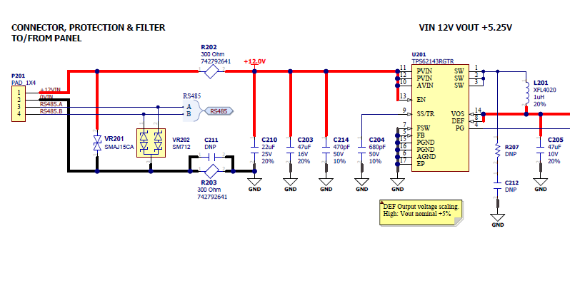
As some of the units died at a customer installation this is a quite urgent issue for us so your help is most appreciated.

kind regards

Hans

  • I'll check with Mike and Jack to see what you have discussed with them.

    Failures of DC/DCs are usually caused by PCB layout and/or hot-plug overshoot on Vin. If Vout goes above the abs max limit (for the VOS pin, in this case), this can also cause damage.

    Can you try and re-produce another failure, while monitoring Vin, Vout, SW, and PG when it fails? You can likely trigger on Vout falling to trigger the scope to catch the point of failure.
  • Hi,

    unfortunately no - this issue hardly ever happens so it is very difficult to replicate. We still can not exclude the power supply of the customer completely. Some of the readers only failed after weeks in the field.

    Because of that we wanted to know spike on the output of the TPS62143 could kill the IC and what sort of amplitude such a spike would need to have (so far we did not see any).
    In addition we wanted to ask if the inductance of the speaker could cause a problem with the loop stability of the regulator. The supply circuit as well as the speaker driver and LED driver schematics are attached.

    all the best!
  • Ah, it sounded like you were able to reproduce it in your lab with a defined combination of events.

    The VOS pin is rated to 7V, so spikes above this could cause damage.

    You can examine the output voltage for oscillations, etc. while the audio is running to check stability. I think this will be fine.
  • Hi,

    We also found this E2E case:
    e2e.ti.com/.../1013715

    Is it possible that this IC has some issues. Or layout as well as our schematic have been reviewed by TI support. We can get units to fail by stressing them regularly by now. The current consumption of our circuit always stays below 1A. So far we have not seen a single spike on the input nor the output the caused the death of a regulator.

    With units in the field and with the customer this becomes an ever more worrying issue. We also conducted temperature tests of the design and found no problems there. Even at loads much higher than we experience in the application we stay well clear of the maximum junction temperature (even at 85C environment temp). The units however fail at room temperature.

  • Hi,

    Please see below the triggered death event. As you can see from the scope plot the 5.25V as well as the input look clean. We triggered on the falling edge of the output voltage to show us when the device died:

    Is there any chance that the FETs used for switching are both on at the same time due to an issue:

  • Thanks for capturing a failure. What did you have to do to cause this to happen? If anything is proprietary, go ahead and start a 'conversation' with me to discuss further.

    Are you able to fairly easily cause a failure in your lab? It's unclear from the last few posts.

    If you can cause another failure, can you trigger at ~1 usec/div and add the SW node to the scope?

    Can you send me your layout to check again? I don't believe I have seen it before.

    It seems like Mike is on holiday for a little while longer, but he might help you debug when he is back.
  • Hi,

    It is not easy - if we keep 24 units running for about 12 hours (under constant stress condition = RFID reading, LEDs swicthing, sound playing) about a handful of them die. Whether a scope is connected to a dying unit is pure luck. If we replace the DC/DC converter on a dead unit it functions normally again. We can try to monitor the SW node - but again it may take days until we are lucky to catch a failure.

    The layout was reviewed by TI support before with focus on EMC. I can share the gerber again - but I would rather send them to you directly as this is a customer project under NDA. So we will need to obscure some parts.

    kind regards
  • Hi,
    What could theoretically cause both FETs in the SW control to be "ON" simultaneously? And would a lower input voltage make such a scenario less likely?

    Thanks!
  • Sure, we can discuss the layout on the private message system. There's no need to discuss your specific system details here on the public forum.