This thread has been locked.

If you have a related question, please click the "Ask a related question" button in the top right corner. The newly created question will be automatically linked to this question.

Control strategy for a 3 phase asynchronous buck converter

Other Parts Discussed in Thread: POWERSTAGE-DESIGNER

Hi, 

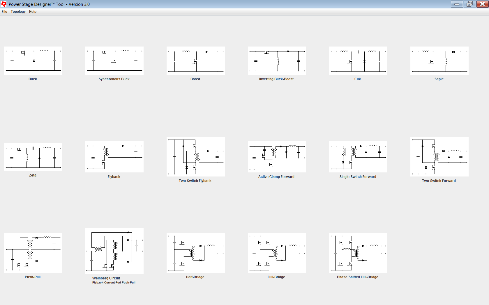
I'm looking to make a prototype DC-DC step down converter for power regulation in a induction heater. I chose a 3 phase buck topology so I can reduce the choke size and get better efficiency. I will use a delfino MCU and the sigma delta iso adc to get the current in every phase. My specification are: 

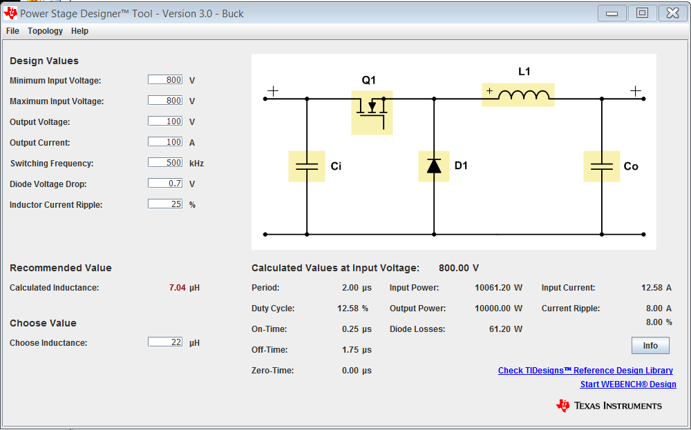
Input: 800V form a 3 phase Boost PFC

Output : ideally (0-800) really (100 - 750), while keeping the output power constant at 10KW. So that makes the current form 100A (@100V)- 12.5A (@750V) for full power. The voltage and current ripple do not have to meet any stringent requirements. 

My question is, how do you decide when will you shut down the phases to get the best performance - especially efficiency. I read on a couple of online sites different approaches and I'm a bit confused. Would it be correct to say that the goal is to keep the phase currents as low as possible without going to DCM mode? 

E.G. If we have inductor ripple current of 5A. If I would need 12 A peak together I would use 2 phases (180 deg phase shifted) to get 6A pek per phase and so I would still stay in CCM. Because if I used all 3 phases, that would mean 4A per phase, and the converter would go to DCM. But if I needed 50A then I would use all 3 phases. 

Also why is CCM preferred to DCM (if we ignore the more complex regulation requirement as my system does not need a good dynamic response)? In SLVA057 it states "It should be noted that the buck power stage is rarely operated in discontinuous conduction mode in normal situations, but discontinuous conduction mode will occur anytime the load current is below the critical level." why is this?

Is CCM more efficient then DCM or is it roughly the same? 

What are more in depth differences of CCM vs DCM (radiate noise? over voltage peeks? The stuff that they don't say in textbooks.)

Best regards, 

Marko 

  • Hello,

    It’s a bit of an open ended question as this will certainly depend on the AC and DC losses. By AC, I am referring to things like Switching losses, Transitional Losses and Core Losses in your magnetics. And DC losses are referring to Conduction losses in your FETs, Diodes and DCR of your magnetics. The reason why it depends on this is because the ratio between these will dictate your Efficiency (y axis) vs. Load current (X axis) curve. For example if you have low AC losses, typically you will have higher DC losses due to the figure of Merit (FOM) between RDSon and Gate charge of the FETs selected, and the core losses being low, typically means a higher inductance which means more turns yielding higher DCR losses. What this does to your efficiency curve is it yields efficiency relatively higher at lower currents and lower at higher currents compared to the converse set up of lower DC losses and higher AC losses (Lower efficiency at light load and higher efficiency at high load currents). The reason why I am talking about this is because you ultimately want to phase shed at the point the efficiency curve starts to dip due to the AC losses. It is at this dip point that it is best suited to shed a phase. If I were you, I would design the shedding of phases circuit such that its adjustable and once you get your actual efficiency profile you can make the best determination of when to shed the load to maximize efficiency. Hope this helps you with a strategy going forward? Perhaps a pic paints a thousand words here, let me know if you follow what I am saying?

  • Picture paints a thousand words, please see attached.  Hope this makes sense

    1447.Phase shed example.docx

  • Hi, its me MarkoAnte I forgot my log in info from work.

    Ty for the help, but how do I then decide on the inductors and capacitor values? Any tips? I can calculate L and C, for a simple buck, but with the changing output voltage and the 3 phases I'm lost and don't know where to start. Could webench help me in some way?

    Could you please shed some light on the CCM vs DCM question form above? Would I try to always be in CCM then?

    In the simulation I was playing with around 3x1mH and 100uF am I in the ball park ?

    Best regards,
    Marko Ante
  • Webench will not help here given your input voltage. However for deciding your L and your C, you will need to decide on your topology first. Once you have decided, I would divide your output current by the number of phases and treat it as a single phase for the design and then replicate the design for the phases you intend to use. From there you will need to select your L and C values. Compensation gets a little trickier, but usually there is material that addresses multiphase, especially for a buck and a boost. However, given the input voltage, I suspect you will have to go with an isolated topology? Of which this question should be raised in the isolated forum, if indeed you intend to use an isolated topology?
  • My topology will be buck, the isolation to the user will be done with a HF transformer that feeds the resonant circuit at the output of the induction heater.
    What is this compensation you mentioned?
  • It will really depend on the controller you select. As mentioned I do know of a Buck controller that can work at a Vin of 800V? However if you are looking into a general theory on compensation, please see link below. Hope this helps?

    www.ti.com/.../slup340.pdf
  • Hi, 

    this compensation goes mostly for analog design. I'm going to use a MCU do control it. 

    Best regards, 

    Marko

  • Hello Marko,

    Try the POWERSTAGE-DESIGNER tool.

    This allows you to experiment with different topologies.
    You enter Vin Vout Iout Fswitch and a few other parameters.
    The tool recommends a minimum inductance, calculates power stage voltages and currents.

  • O thank you,
    suck a great software. This will give me some good values to put into simulation.

    Best regards,
    Marko
  • But still this does not answer my original question, let me try to illustrate it better.  Lets say the L = 1.5mH, for 20kHz, I get the following:

    Duty/ IL ripple Vout P = 10kW P = 5kW P = 1kW
    0.125/ 2.9A 100V 100A(3f) 50A(3f) 10A(1f)
    0.5/ 6.6A 400V 25A(1f) 12.5A(1f) 2.5A(DCM)
    0.94/ 1.56A 750V 13A(1f) 6.5A(1f) 1.3A(DCM)

    The (3f) and so on,  show how many phases can be active to still be in a 30% IL ripple constraint.

    But lets say that at 5KW at 400 V i would use 3 phases, that would but me into DCM. This is not desirable, right? Because if it is, then I could further reduce the inductance.

    Hope this makes my question more clear.

    Best regards,

    Marko  

  • DCM in itself is not an undesirable mode of operation. However in DCM peak current will increase as you reduce your inductor and as mentioned the AC losses will increase. You will need to know what the losses are with a selected inductor and determine where on the efficiency curve you are in order to know where to most efficiently shed a phase.
  • As the graph that David provided, the phases should be dropped when total system efficiency start to suffer.

    You may be able to model the total system, PFC front end and multiphase DCDC.
    Understand where the losses are.
    Create graphs of efficiency at various loads to determine the points where you want to start shedding.
    Its not just the DCDC's, but the front end must be considered for its contribution.

    Bottom line is, you shed phases when you need to.

    DCM operation is not undesirable.
    The loop gain of a buck converter is reduced in DCM, slowing its transient response rate.
    But DCM can be more efficient.

    Many times you start shedding phases when the mosfet gate drive power and switching losses start to dominate at light load.
    So the system phases will have CCM DCM, pulsed or off mode.

    I would create a design prototype that is flexible so you can change components.
    Do some testing; Efficiency Vs Vin Vs Vout Vs Iout, drop some phases and create an efficiency graph of the system.
    With a uC in charge it can decide when to start shedding.

    There will be some iteration in this process.

  • Thank you EdWalker, for your great explanation.

    So then what parameter would you look at for choosing the inductor value? In my sistem ripple is non-critical. As the mass of the work peace being heated smooths all "fast" power variances.  

    Would looking for a good bang for buck output capacitor - a good capacitance/max ripple current for price - and then choosing the inductors so that the capacitor ripple current does not exceed half the max current allowed be a good idea? 

    E.G. Lets say that I have a capacitor for 40A ripple at 20 kHz and then I chose a inductor so that the ripple current (at worst case) is 20A. 

    Best regards, 

    Marko 

  • Hello Marko,
    Component selection is a complete exercise in itself.
    If your company has a components group you should work with them.
    You probably have some preferred vendors that will help guide you to cost effective solutions.

    At 10KW and 800V, even with 3 DCDC phases, you will need high voltage high current devices and your choices will be limited.
    It may help to review components used in some TI reference designs.

    TI's Applications area has many design examples.
    www.ti.com/.../reference-designs-selection.page
    Automotive HEV EV Powertrain is one area that would have high voltage high current areas.

    Vienna Rectifier-Based Three Phase Power Factor Correction Reference Design Using C2000 MCU
    This design is one of many high power examples.
    www.ti.com/.../TIDM-1000


    Using other designs as reference, you can make a first attempt at choosing the RIGHT parts for the design.
    Don't worry about cost too much to begin with, you want to make the design work first.
    Then once you have a good hardware platform is the time to start scrubbing the components for cost and availability.

    Have a great weekend.