This thread has been locked.

If you have a related question, please click the "Ask a related question" button in the top right corner. The newly created question will be automatically linked to this question.

TPS54260: Input enable/UVLO resistor divider calculation

Part Number: TPS54260

Hi 

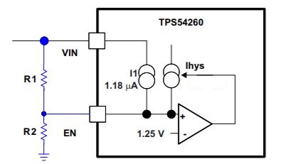
I am using TPS54260 in my design for the 3.3V conversion, The input voltage may change between : 4.5V to 16V(13V nominal);

Load current: 1A

Output voltage: 3.3V

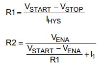
How to calculate the enable pin voltage divider by considering input variation as well as UVLO,

Note: Convertor should be in on conditon allways.

The formulas provided in the data sheet are confusing,

pls provide some example calculations 

Regards,

Rajesh

  • Rajesh ,

    In your application , if you want your design to be enabled at 4.5V(Vstart)  and disabled when voltage goes below 4V (Stop) , you can program the UVLO as below :

    where ihys is 2.9uA ,  Vena is enable threshold of 1.36V and I1 is equal to 1.18uA .

    --Ambreesh 

  • Hi,

    Thanks for sharing the feedback. I have calculated the design parameters based on the datasheet formulas: those are listed below, please any one verify & correct me if I am wrong:

    Input voltage:14

    Output voltage:3.3

    Load current:1A

    FSW: 1918KHz

    Rt: 54.9K

    Enable pin calculations:

    Vstart: 4.4

    Vstop:4

    RUP:121K

    Rdown:52.3K

    Feedback resistor calculation:

    R1: 182K

    R2:57.6K

    Output inductor: 6.8uH(MAG-IND,6.8uH,20%,1.6A,SMD)

    Ripple voltage: 3%

    Ripple current: 30%

    Cin: 400uF

    Cout: 220uF+10uF+10uF+10uF

    Compensatoin loop values:

    Rcom:15K+10nf 

    Regards,

    Rajesh

  • Rajesh ,

    Your Max Input voltage is 16V . At 16V input and 3.3V output with Fsw-2Mhz , you end up having on time of 100nS which is lower than the typical on Time value of 135nS for this device . I recommend using lower switching frequency .
    You may use Webench for circuit design and simulation .

    ---Ambreesh