This thread has been locked.

If you have a related question, please click the "Ask a related question" button in the top right corner. The newly created question will be automatically linked to this question.

BQ24166: Battery Charging Query

Part Number: BQ24166

Hi,

We are using BQ24166 for one of our project. We are using a 3.7V Li-Po Battery for charging. We found that it is taking much time for recharging the battery to 100%. When we check the battery after charging for a period of 12 Hrs still the battery voltage shows as 4.17V. It is not attaining the Full battery voltage of 4.2V. Since in our case the Battery life matters a lot can you please comment on this issue. How can we attain the full battery level ie 4.2V.

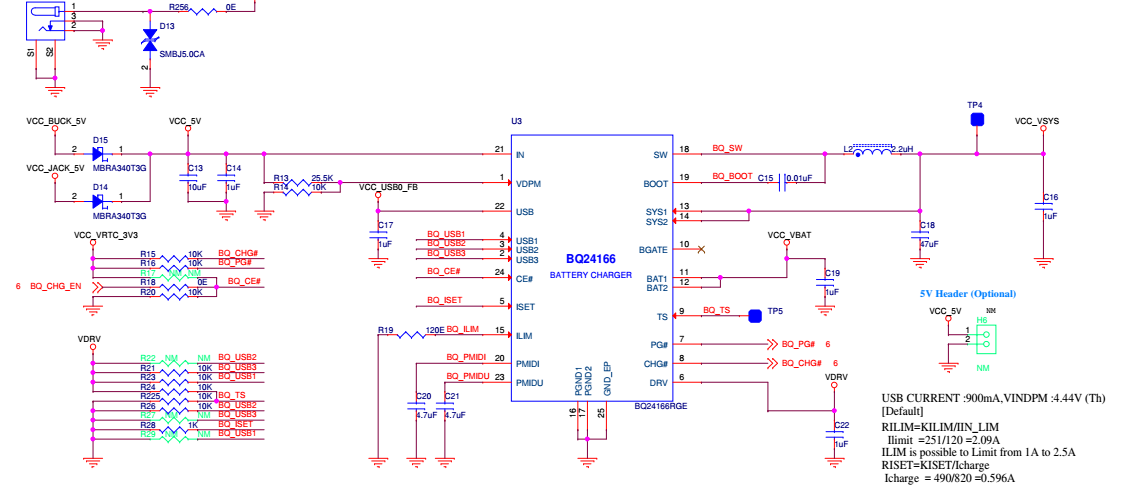
Since some of our parts operates on a voltage of 3.3V minimum, we are making our system to operate between a voltage of 3.4V to 4.2V. So we are taking the 3.4V as the battery low level and 4.2V as the battery full level. Is our method correct? Can you please comment on this. Attaching the charging circuit and the battery specs.

  • Hi Johny,

    Sorry to hear you are having trouble. Is the /CHG pin low (indicating still charging) or high impedance (indicating charge termination)? Is this at 25C? If /CHG pin is high impedance and ambient temperature is not 25C, 4.17V is within the ICs battery regulation tolerance of 4.16V to 4.24V over full temperature range.
  • Hi Jeff,
    Thank you for your response. The /CHG pin is indicated low only. And the board temperature will be above 25C. And also if we keep it for some days we can see that the CHG pin becomes high. Can you see any issue in the scheme we have implemented? The battery is getting charged above 4.2V when we charged it externally. So it must be the charging IC which is limiting it to charge upto 4.2V, ryt? Please comment on my understanding.
    Also please clear my doubt. The CHG pin high during charging phase an once it is fully charged it becomes low. and soon if the the voltage drop below 4.2V again the charging will be enabled? and CHG pin will be high?
    We have not provided NTC pin. and we have given a resistor divider option on the TS pin. will these affect the performance of charging?
  • If the TS function is not used, then TS pin needs an equal sized resistor divider from DRV to TS to GND.  /CHG pin should be low (allowing current to flow through an LED to ground and turn on, for example) during charging and goes high impedance (HiZ) at termination or fault states.  The charger charges the battery up to VBATREG which is 4.2V typical.  There is a safety timer that expires after 6 hours typical and will cause the /CHG pin to change to HiZ.

    If there is high impedance between the BAT pin and the battery (including internal battery impedance), the time spent in constant voltage (CV) mode is extended.  Can you provide a scope shot of SYS, BAT and VIN when V(BAT) = 4.17V on 1V/div and 1 ms time scale? 

  • Hi Jeff,

    We had done a thorough check in the behavior of the Battery charging. Below are our observations.

    The battery was put in charging mode from 3.7V . The charging was done through 2A USB Adapter. We continuosly charged it for about 6 hours and when it reached 4.181V the /CHG pin became high. But after sometime the battery voltage was reduced to 4.7V which was still powered from external adapter. We observed that soon after the /CHG pin goes high the battery starts discharging, even if the input supply is connected.

    -Is this behavior of battery discharging soon after charge stop normal or is it an issue?

    -Is there any dependency in charging through USB and through VIN Supply? We have IUSB limit as 900mA.

    Below i am sharing the values of voltage while the CHG pin is high and when it is low. Please see and comment on the issue.

    Since we have got a offset issue in our MSO i will send the scope shot after correcting it.

    1). While CHG is Low

    Vsys=4.236

    Vin=5.071

    Vbat=4.181

    2) While CHG is High (Soon after half hour)

    Vsys= 4.143

    Vin=4.878

    VBat=4.181

    The below is the scope shot taken while charging. The actual value of Vbat is 4.18V. scope shot values are having an offset of 0.01~0.02V. Corrected values will be shared soon. Mean while please comment on the discharging issue mentioned above. 

  • Hi Johny,

    Based on your scope plot above with the squarish waveform on SYS and spikes on VIN, I see that the IC has activated the reverse boost prevention circuit, as described on datasheet page 23. When that circuit is active, the BAT/SYS pin consumes more current. The charger may not accurately terminate at ITERM or report termination but will maintain the battery voltage between the recharge voltage (4.2V-120mV) and full charge voltage. Reverse boost prevention activates more frequently with batteries having high impedance, either through the connections or internal.
  • Hi Jeff,

    We were checking the battery performance in different use cases. We found that when we increased the charging current to 1.6A, it was charging fast. But we found that after /CHG becomes highh and when we check the battery voltage, it was 4.10V. there was no reverse current flow from the battery after the /CHG became high. But in another test case we saw that, when the Vbat voltage came to 4.18V and /CHG became high. But after this state there was a 30mA current flow from the battery to the device eventhough the input supply was present. Can you please comment on both these test case. What could be the possible reasons for this kind of behaviour?

    Also can you suggest some tips or solutions to resolve the reverse boost prevention? what all we need to take care.

  • Johny,

    First, do you have a current meter from BAT pin to battery? If so, please remove it, replace with a small resistor (0.01ohm - 0.1ohm) and measure across it with a volt meter to measure current OR use an oscilloscope current probe . A series current meter has too much resistance and/or auto-ranges which causes problems for any battery charger.

    Regarding /CHG going high when battery is 4.10V (assuming no current meter installed), are you measuring the battery voltage at the IC BAT and GND pins? The IC's constant voltage mode can only regulate the voltage at the charger's BAT pin. Also, at what voltage is TS pin? If TS pin is low, indicating battery temperature is high, the regulation voltage is automatically reduced to 4.10V. As per table 4 on d/s page 24, the /CHG indicator only goes low during the first charge cycle (i.e. charging after input power is applied). If you remove and replace input power, does /CHG change state?

    Regarding V(BAT) = 4.18V, /CHG being high and 30mA into BAT pin, if the waveform on SYS is like the one in your previous post (and d/s figure 25 on d/s page 23), then the IC is in reverse boost prevention. However, I have never seen the IC consume as high as 30mA in reverse boost prevention. Lowering battery resistance/impedance from BAT pin to battery connection reduces the likelihood of entering reverse boost prevention. Increasing the termination current is another way to reduce the likelihood of entering reverse boost prevention. With the standalone bq24166 having ITERM~=10% x ICHRG, the only way to increase ITERM is to increase ISET resistor after the battery reaches constant voltage mode. This will require at least an extra transistor and some resistors to accomplish.
  • Hi Jeff,

    When we checked with the battery during charging following were our observations which include the response for your queries.

    We started charging the Battery from 3.125V(standalone battery voltage).
    When connected to 5V input supply for charging, the charging current to battery was 0.88A, Vbat = 4.187V.
    After 4Hrs the Vbat came upto 4.192V. and after 5 hrs when we checked the Vbat voltage was 4.10V and /CHG was pulled high. TS pin was 2.48V.
    But when we power cycled the device the /CHG pin again become low and started charging again. After one hour again the /CHG pin became low where Vbat was about 4.12V. Once again when Input supply was reconnected the CHG pin became low and it continued charging for one hour when Vbat was 4.133V and CHG was high. After that when reconnecting the input supply the CHG was not going low. All the Vbat voltage mentioned is the voltage at the IC Bat pin. When the battery was measure after removing the voltage across the battery was 4.133V.

    What could be the reason for this kind of behavior? Any clues? Does the battery play a role in this? We are now checking with different batteries.
  • Johny,

    With high impedance connection from BAT pin to battery (including impedance in the battery itself), the reverse boost circuit activates and prevents the charger fully charging. The screen shot you included in previous post confirms that the reverse boost circuit is active.
  • Hi Jeff,
    We are using this for a Doorbell Device application. When we are connecting it directly to the Chime supply we could see that the Doorbell chime energizes and rings at one point. This happens when the Battery charge is low and the Battery voltage at 3.5V approx. So to avoid this we made the charging current limit as 490mA. But in that case the battery charging time was more. So we increased the charging current limit as 1.5A. But in that case the chime starts ringing when the battery is getting below 3.5V. This is our issue.
    So to avoid this we were planning to change the Iset charging current limiting resistor on the go. ie during chime connected supply the current limiting resistor(Riset) will be 1k(490mA charging current) and during USB charging Riset will be 300Ohm(1.633A charging current).
    We are planning use SPDT switch to switch between these resistors. I would like to know your comment on this. Will this be a good solution?
    Is there any issue in changing the resistor during the working condition?
    Will this cause any other issue during charging?
    How charging IC identifies the current limiting resistor? Is it during the initial charging time or will it check during often intervals?
  • Dynamically changing ISET resistance is no issue. The ISET current/voltage is a function of charge current all the time.

  • Hi Jeff,
    Since we are facing the chime ringing issue we were planning to reduce the charging current. That is to reduce the Icharge current. For this we were planning to set it as 300mA or below. But in the datasheet the operating range of Icharge is mentioned as 550mA to 2500mA. Is there any problem if we set it below the suggested 550mA current. How will this affect the battery and the IC performance.
  • Johny,

    TI does not test charge accuracy below 550mA in the datasheet. The IC will still charge and terminate but the charge current and termination accuracy will be worse. I do not have any data on charging and terminating at lower charge currents.
  • Thank You Jeff for your help.
    We are designing the device as a Doorbell. We were planning to go for certification. We were planning to go for California Energy Commission C certification. Is there any documents related to this for BQ24166 Charger IC. Also is there anything we need to take care while going for the certification using this IC. You have any comments on the Certification of th IC ?
  • Johny,

    Unfortunately I do not have documents related to the California Energy Commission C certification.

  • Hi Jeff,

    We were planning to go for certification. So we want to know if BQ24166 IC has passed the certification or is it a pre certified IC?

  • The bq24166 has not been certified by TI and I am not aware of a customer who has certified this charger in their system. The charger was developed and released in 2011 which, I believe, was before the certification.
  • Hi Jeff,

    Is there any other Battery charging IC similiar to BQ24166 which has done the certification? (CEC certification)