Hi,
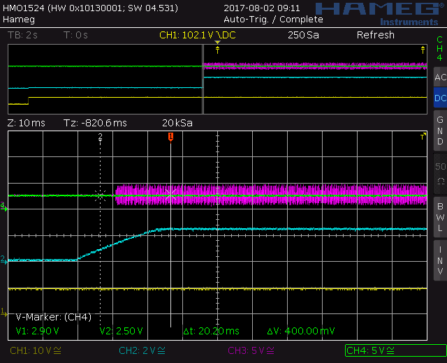
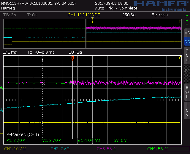
we have a circuit with a large capacitor (2.5F) as short-duration power source. The intended operation after applying VIN to the circuitry is to charge this capacitor with constant current to 5V and afterwards start the cpu module. Under most conditions this works as intended:
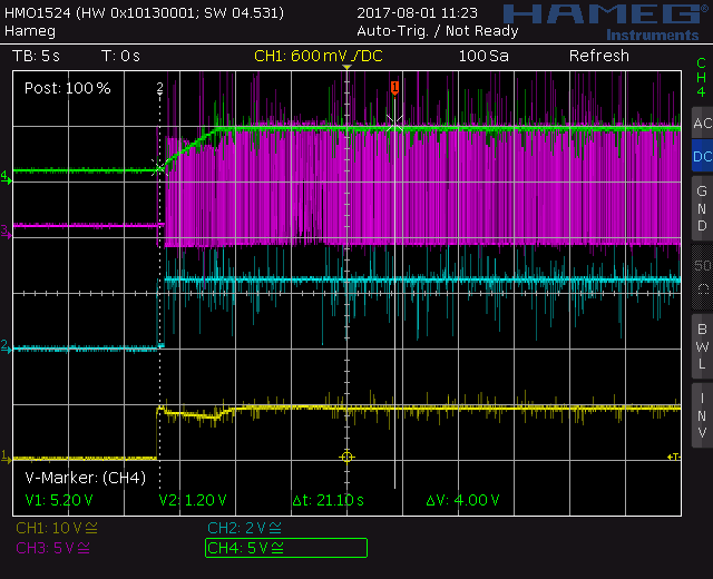
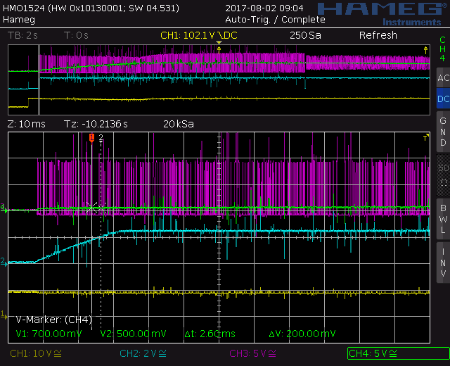
yellow: VIN, blue: SS, magenta: SW, green: VOUT
Under some circumstances precharging the load-buffering capacitor fails. This might (not sure about it) be caused by remained charge in the load-buffering capacitor:
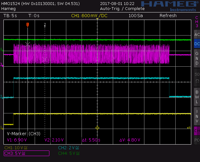
In this cases the SW voltage does neither reach VIN nor GND and the load is not charged at all.
Can this be caused by load-side voltage in an inappropriate window at circuitry startup?
Kind regards, thanks for any help
Arndt