A related question is a question created from another question. When the related question is created, it will be automatically linked to the original question.
If you have a related question, please click the "Ask a related question" button in the top right corner. The newly created question will be automatically linked to this question.
Below is my initial feedback and follow-up questions:
What is the TPS65217 powering? An AM335x processor?
Why was the -B revision selected?
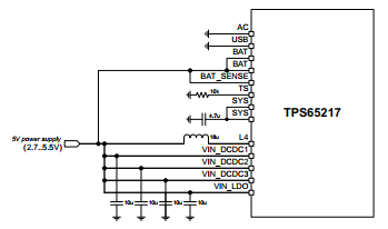
Was a reference design used to create this schematic? If so, was it the Beagle Bone Black or the TPS65217BEVM?
Is DDR memory used? If so, which version (DDR2, DDR3, or other)?
What is the current needed for LED strings? Resistors for ISET1/2 do not need to match. If 121k is connected to ISET1 for Low current, then 64.9k can be connected to ISET2 for High current option. Datasheet explains that ISINK1/2 are always the same value, but can be set to Hi/Lo value with ISET1/2
Is there a physical push-button connected to PB_IN? Net name has a typo: "PB_INT". This is not an interrupt, but an active-low edge-triggered push-button press.
Will USB_DC (connected to USB pin) and DC_IN (connected to AC pin) be used simultaneously? Datasheet has a caution note about this configuration.
Cannot comment on any connections to PWR_EN, PB_IN, PGOOD, LDO_PGOOD, WAKEUP, INT, or MUX_OUT because bus named POWER_CONT goes off-page to pages 2,3,5.
Yes, the -B revision of TPS65217 does power the AM3354-ZCZ. But the -C and -D versions also power the AM3354-ZCZ.
The difference is whether you want to use DDR2 (-B version), DDR3 (-C), or DDR3L (-D) memory.
If "LPDDR1" memory operates at 1.8V (same as DDR2), then the -B version of the TPS65217 is the right choice.
For 20mA LED current, I recommend setting RISET1 = 130k (Low - 10mA) and RISET2 = 64.9k (High - 20mA) and flipping the the ISEL bit to '1' before enabling the LED strings by flipping ISINK_EN to '1'.
If only using USB_DC, I recommend re-wiring the schematic so VBUS of USB connects to the BAT pin, as shown in Figure 56 (Case 3) on page 77 of the datasheet:
This will prevent an unintended switch-over from USB to BAT during unexpected un-plug/re-plugs of the USB plug, which may cause a brown-out and temporarily lock-up the device.
Pressing the PB_IN push-button will resolve the lock-up because BAT is stuck as the power supply and requires a push-button press to begin the power-up sequence. Case 3 wiring will avoid the lock-up entirely, so it is preferred, but the Push-Button will still be required.
Please ensure connections to the CPU I/O follow the AM335x recommendations for PWR_EN, PB_IN, PGOOD, LDO_PGOOD, WAKEUP, INT, or MUX_OUT. For example, PWR_EN on the TPS65217 connect to PMIC_PWR_EN on the AM335x.