Other Parts Discussed in Thread: BQSTUDIO, BQ78350-R1, BQ78350
Hi Team
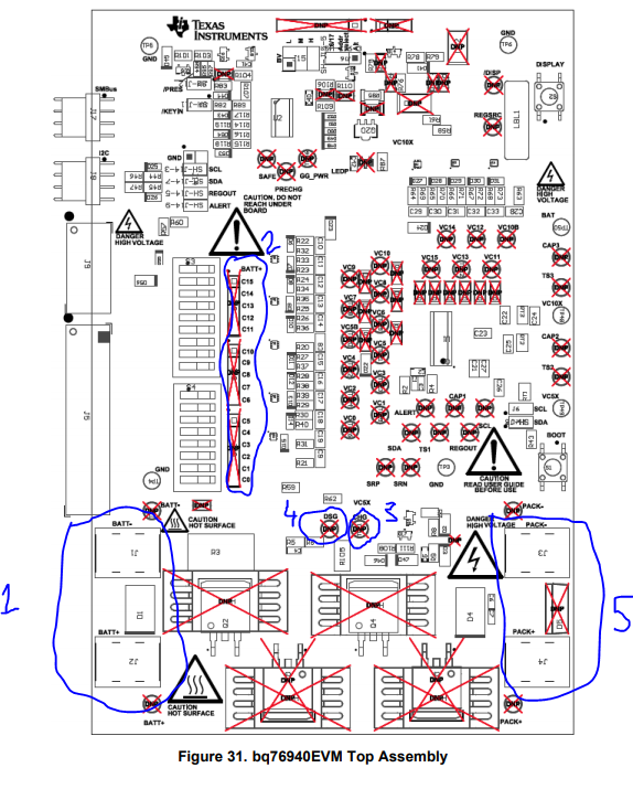
I would like to communicate my raspberry pi 3 microprocessor with 78350-R1 microcontroller present in BQ76940EVM which is connected to 15 cells in series. I would like to know the following things listed below
1. What all libraries should be included for i2c communication
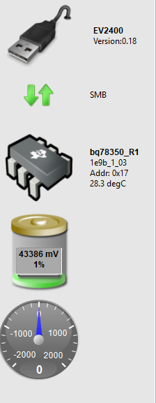
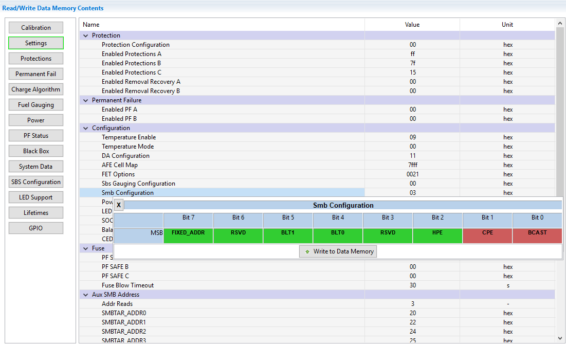
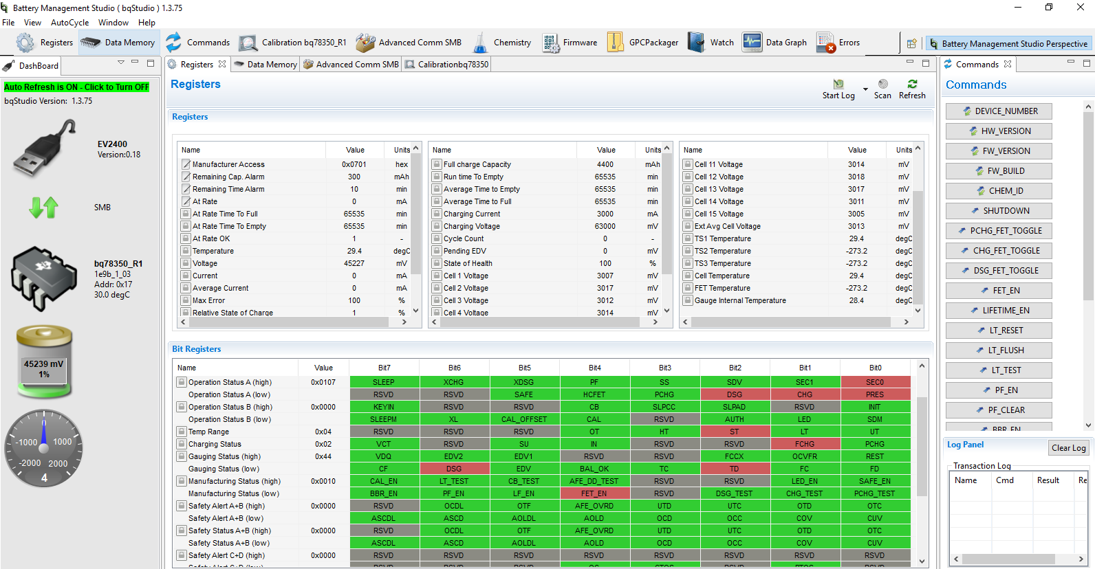
2. Presently I can detect 0x08 address from my raspberry pi when I connect to i2c port and 0x0b address when I connect with SMBus port. I want to read the cell voltage, SOC and temperature values which are showing in the bqstudio. What are the registers which we need to call to read the value. What should be the data memory smb configuration setting. Below you can see the register values are having an lock icon.Does that mean its not accessable. 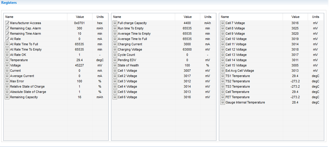
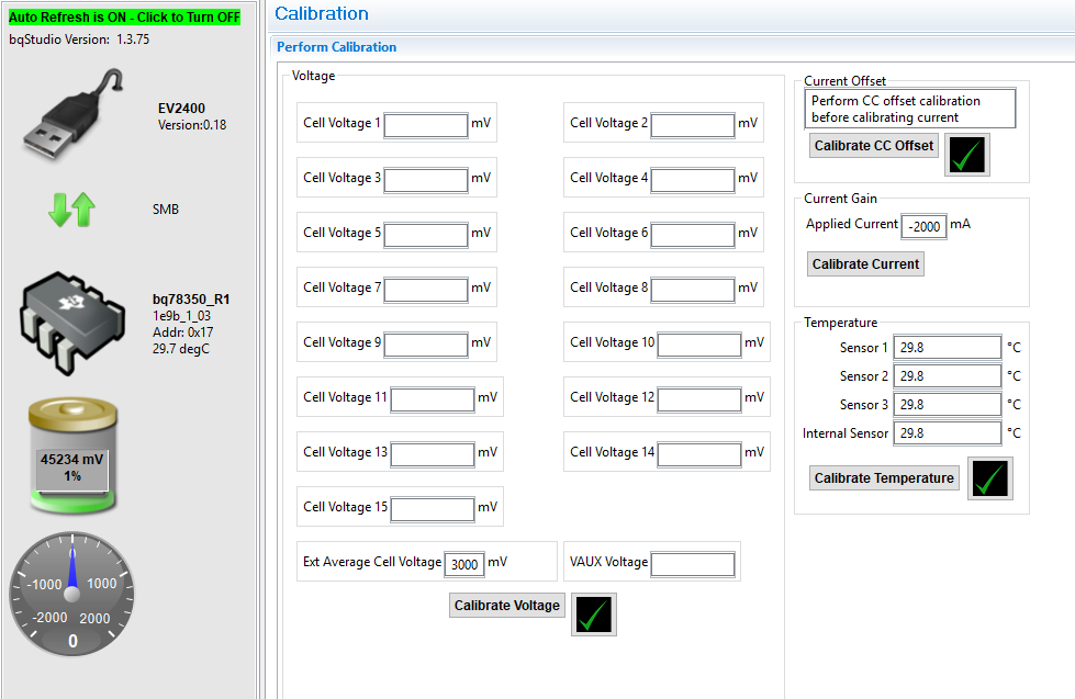
3. In gauge calibration, I have calibrated voltage, temperature and current offset. In case I am unable to do the current gain calibration does it stop the communication? do I need to set some control flag. I dont have a power resistor currently to do the current gain calibration with constant current flow. Is that the step which should be done prior to do communication. Is there some method to bypass it.
4. What are these addresses?Are they which I need to access? .
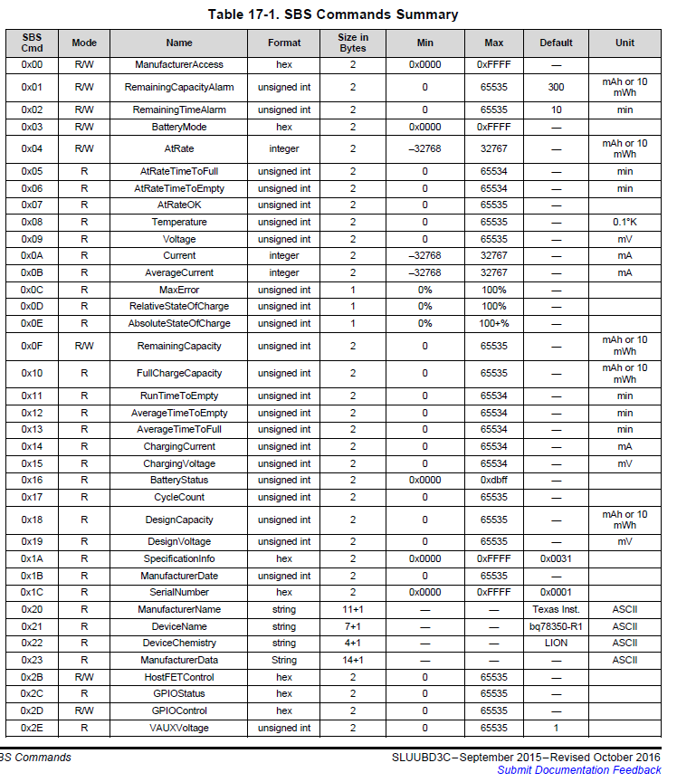
5. I am following the sluubd3 manual. Do we need to read the entire data inside these addresses
6. The code is attached for your reference. We are further storing the data in cloud so it includes that part as well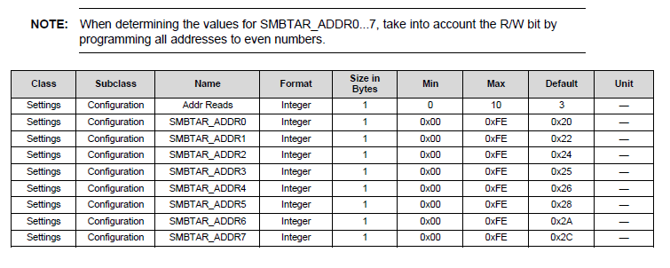
*
* Copyright 2010-2015 Amazon.com, Inc. or its affiliates. All Rights Reserved.
*
* Licensed under the Apache License, Version 2.0 (the "License").
* You may not use this file except in compliance with the License.
* A copy of the License is located at
*
* �http://aws.amazon.com/apache2.0
*
* or in the "license" file accompanying this file. This file is distributed
* on an "AS IS" BASIS, WITHOUT WARRANTIES OR CONDITIONS OF ANY KIND, either
* express or implied. See the License for the specific language governing
* permissions and limitations under the License.
*/
/**
* @file shadow_sample.c
* @brief A simple connected window example demonstrating the use of Thing Shadow
*/
#include <stdio.h>
#include <stdlib.h>
#include <ctype.h>
#include <unistd.h>
#include <signal.h>
#include <memory.h>
#include <sys/time.h>
#include <limits.h>
#include <linux/i2c-dev.h>
#include "aws_iot_log.h"
#include "aws_iot_version.h"
#include "aws_iot_shadow_interface.h"
#include "aws_iot_shadow_json_data.h"
#include "aws_iot_config.h"
#include "aws_iot_mqtt_interface.h"
/* Initialising wiring library*/
#include "/home/pi/wiringPi/wiringPi/wiringPi.h"
#include "/home/pi/wiringPi/wiringPi/wiringPiI2C.h"
/*!
* The goal of this sample application is to demonstrate the capabilities of shadow.
* This device(say Connected Window) will open the window of a room based on temperature
* It can report to the Shadow the following parameters:
* �1. temperature of the room (double)
* �2. status of the window (open or close)
* It can act on commands from the cloud. In this case it will open or close the window based on the json object "windowOpen" data[open/close]
*
* The two variables from a device's perspective are double temperature and bool windowOpen
* The device needs to act on only on windowOpen variable, so we will create a primitiveJson_t object with callback
The Json Document in the cloud will be
{
"reported": {
"temperature": 0,
"windowOpen": false
},
"desired": {
"windowOpen": false
}
}
*/
#define TOTALCURRENTCAPACITY 74
#define TOTALENERGY 3750 ����//3.75kWh
static void energyCal(float *amps, float *voltage, float *amphr, float *energy, float *battery_state){
float totamps = 0;
float totvoltage = 0;
float power = 0;
float tot_power = 0;
float energy_left = 0;
float time_left = 0;
�������� power = (*voltage) * (*amps);
��� tot_power = tot_power + power;
//*energy = *energy + *voltage * (*amphr); �������//direct input from bms - no not needed currently
��� energy_left = TOTALENERGY - *energy; //if we get direct energy, we just calculate energy left
}
void ShadowUpdateStatusCallback(const char *pThingName, ShadowActions_t action, Shadow_Ack_Status_t status,
��� ��� const char *pReceivedJsonDocument, void *pContextData) {
��� if (status == SHADOW_ACK_TIMEOUT) {
��� ��� INFO("Update Timeout--");
��� } else if (status == SHADOW_ACK_REJECTED) {
��� ��� INFO("Update RejectedXX");
��� } else if (status == SHADOW_ACK_ACCEPTED) {
��� ��� INFO("Update Accepted !!");
��� }
}
void windowActuate_Callback(const char *pJsonString, uint32_t JsonStringDataLen, jsonStruct_t *pContext) {
��� if (pContext != NULL) {
��� ��� INFO("Delta - Window state changed to %d", *(bool *)(pContext->pData));
��� }
}
char certDirectory[PATH_MAX + 1] = "../../certs";
char HostAddress[255] = AWS_IOT_MQTT_HOST;
uint32_t port = AWS_IOT_MQTT_PORT;
uint8_t numPubs = 5;
void parseInputArgsForConnectParams(int argc, char** argv) {
��� int opt;
��� while (-1 != (opt = getopt(argc, argv, "h:p:c:n:"))) {
��� ��� switch (opt) {
��� ��� case 'h':
��� ��� ��� strcpy(HostAddress, optarg);
��� ��� ��� DEBUG("Host %s", optarg);
��� ��� ��� break;
��� ��� case 'p':
��� ��� ��� port = atoi(optarg);
��� ��� ��� DEBUG("arg %s", optarg);
��� ��� ��� break;
��� ��� case 'c':
��� ��� ��� strcpy(certDirectory, optarg);
��� ��� ��� DEBUG("cert root directory %s", optarg);
��� ��� ��� break;
��� ��� case 'n':
��� ��� ��� numPubs = atoi(optarg);
��� ��� ��� DEBUG("num pubs %s", optarg);
��� ��� ��� break;
��� ��� case '?':
��� ��� ��� if (optopt == 'c') {
��� ��� ��� ��� ERROR("Option -%c requires an argument.", optopt);
��� ��� ��� } else if (isprint(optopt)) {
��� ��� ��� ��� WARN("Unknown option `-%c'.", optopt);
��� ��� ��� } else {
��� ��� ��� ��� WARN("Unknown option character `\\x%x'.", optopt);
��� ��� ��� }
��� ��� ��� break;
��� ��� default:
��� ��� ��� ERROR("ERROR in command line argument parsing");
��� ��� ��� break;
��� ��� }
��� }
}
#define MAX_LENGTH_OF_UPDATE_JSON_BUFFER 200
int main(int argc, char** argv) {
��� IoT_Error_t rc = NONE_ERROR;
��� int32_t i = 0;
��� MQTTClient_t mqttClient;
��� aws_iot_mqtt_init(&mqttClient);
��� char JsonDocumentBuffer[MAX_LENGTH_OF_UPDATE_JSON_BUFFER];
��� size_t sizeOfJsonDocumentBuffer = sizeof(JsonDocumentBuffer) / sizeof(JsonDocumentBuffer[0]);
��� char *pJsonStringToUpdate;
���
��� float current = 0.0;
��� float voltage = 0.0;
��� float amphr = 0.0;
��� float energy = 0.0;
��� float temperature = 0.0;
��� float battery_charge = 0.0;
int fd = 0x08;
wiringPiI2CSetup(0x08);
//wiringPiI2CWriteReg8(fd,0x26,10); // for verification purpose to see if writing to registers is possible...it works!
temperature = wiringPiI2CReadReg8(0x08, 0x08);// reading temperature from BMS
/* Uncomment below when the connectivity works
current = wiringPiI2CReadReg8(fd, );// fill the register address after fd
voltage = wiringPiI2CReadReg8(fd, );
energy = wiringPiI2CReadReg8(fd, );
battery_charge = wiringPiI2CReadReg8(fd, );
amphr = wiringPiI2CReadReg8(fd, );
*/
��� bool windowOpen = false;
��� jsonStruct_t windowActuator;
��� windowActuator.cb = windowActuate_Callback;
��� windowActuator.pData = &windowOpen;
��� windowActuator.pKey = "windowOpen";
��� windowActuator.type = SHADOW_JSON_BOOL;
��� jsonStruct_t energyMonitor;
��� energyMonitor.cb = NULL;
��� energyMonitor.pKey = "energy";
��� energyMonitor.pData = &energy;
��� energyMonitor.type = SHADOW_JSON_FLOAT;
�������jsonStruct_t temperatureHandler;
�������temperatureHandler.cb = NULL;
��� temperatureHandler.pKey = "temperature";
��� temperatureHandler.pData = &temperature;
��� temperatureHandler.type = SHADOW_JSON_FLOAT;
���� jsonStruct_t chargeState;
�������chargeState.cb = NULL;
��� chargeState.pKey = "battery_charge(%)";
��� chargeState.pData = &battery_charge;
��� chargeState.type = SHADOW_JSON_FLOAT;
��� char rootCA[PATH_MAX + 1];
��� char clientCRT[PATH_MAX + 1];
��� char clientKey[PATH_MAX + 1];
��� char CurrentWD[PATH_MAX + 1];
��� char cafileName[] = AWS_IOT_ROOT_CA_FILENAME;
��� char clientCRTName[] = AWS_IOT_CERTIFICATE_FILENAME;
��� char clientKeyName[] = AWS_IOT_PRIVATE_KEY_FILENAME;
��� parseInputArgsForConnectParams(argc, argv);
��� INFO("\nAWS IoT SDK Version(dev) %d.%d.%d-%s\n", VERSION_MAJOR, VERSION_MINOR, VERSION_PATCH, VERSION_TAG);
��� getcwd(CurrentWD, sizeof(CurrentWD));
��� sprintf(rootCA, "%s/%s/%s", CurrentWD, certDirectory, cafileName);
��� sprintf(clientCRT, "%s/%s/%s", CurrentWD, certDirectory, clientCRTName);
��� sprintf(clientKey, "%s/%s/%s", CurrentWD, certDirectory, clientKeyName);
��� DEBUG("Using rootCA %s", rootCA);
��� DEBUG("Using clientCRT %s", clientCRT);
��� DEBUG("Using clientKey %s", clientKey);
��� ShadowParameters_t sp = ShadowParametersDefault;
��� sp.pMyThingName = AWS_IOT_MY_THING_NAME;
��� sp.pMqttClientId = AWS_IOT_MQTT_CLIENT_ID;
��� sp.pHost = HostAddress;
��� sp.port = port;
��� sp.pClientCRT = clientCRT;
��� sp.pClientKey = clientKey;
��� sp.pRootCA = rootCA;
��� INFO("Shadow Init");
��� rc = aws_iot_shadow_init(&mqttClient);
��� INFO("Shadow Connect");
��� rc = aws_iot_shadow_connect(&mqttClient, &sp);
��� if (NONE_ERROR != rc) {
��� ��� ERROR("Shadow Connection Error %d", rc);
��� }
��� /*
��� * Enable Auto Reconnect functionality. Minimum and Maximum time of Exponential backoff are set in aws_iot_config.h
��� * �#AWS_IOT_MQTT_MIN_RECONNECT_WAIT_INTERVAL
��� * �#AWS_IOT_MQTT_MAX_RECONNECT_WAIT_INTERVAL
��� */
���
��� rc = mqttClient.setAutoReconnectStatus(true);
��� if (NONE_ERROR != rc) {
��� ��� ERROR("Unable to set Auto Reconnect to true - %d", rc);
��� ��� return rc;
��� }
��� rc = aws_iot_shadow_register_delta(&mqttClient, &windowActuator);
��� if (NONE_ERROR != rc) {
��� ��� ERROR("Shadow Register Delta Error");
��� }
���
��� // loop and publish a change in temperature
��� while (NETWORK_ATTEMPTING_RECONNECT == rc || RECONNECT_SUCCESSFUL == rc || NONE_ERROR == rc) {
��� ��� rc = aws_iot_shadow_yield(&mqttClient, 200);
��� ��� if (NETWORK_ATTEMPTING_RECONNECT == rc) {
��� ��� ��� sleep(1);
��� ��� ��� // If the client is attempting to reconnect we will skip the rest of the loop.
��� ��� ��� continue;
��� ��� }
��� ��� INFO("\n=======================================================================================\n");
��� ��� INFO("On Device: window state %s", windowOpen?"true":"false");
��� ���
��� ��� energyCal(¤t, &voltage, &hr, &energy, &battery_charge);
��� ��� rc = aws_iot_shadow_init_json_document(JsonDocumentBuffer, sizeOfJsonDocumentBuffer);
��� ��� if (rc == NONE_ERROR) {
��� ��� ��� rc = aws_iot_shadow_add_reported(JsonDocumentBuffer, sizeOfJsonDocumentBuffer, 4, &energyMonitor,&temperatureHandler, &chargeState,
��� ��� ��� ��� ��� &windowActuator);
��� ��� ��� if (rc == NONE_ERROR) {
��� ��� ��� ��� rc = aws_iot_finalize_json_document(JsonDocumentBuffer, sizeOfJsonDocumentBuffer);
��� ��� ��� ��� if (rc == NONE_ERROR) {
��� ��� ��� ��� ��� INFO("Update Shadow: %s", JsonDocumentBuffer);
��� ��� ��� ��� ��� rc = aws_iot_shadow_update(&mqttClient, AWS_IOT_MY_THING_NAME, JsonDocumentBuffer,
��� ��� ��� ��� ��� ��� ��� ShadowUpdateStatusCallback, NULL, 4, true);
��� ��� ��� ��� }
��� ��� ��� }
��� ��� }
��� ��� INFO("*****************************************************************************************\n");
��� ��� sleep(1);
��� }
��� if (NONE_ERROR != rc) {
��� ��� ERROR("An error occurred in the loop %d", rc);
��� }
��� INFO("Disconnecting");
��� rc = aws_iot_shadow_disconnect(&mqttClient);
��� if (NONE_ERROR != rc) {
��� ��� ERROR("Disconnect error %d", rc);
��� }
��� return rc;
}