This thread has been locked.

If you have a related question, please click the "Ask a related question" button in the top right corner. The newly created question will be automatically linked to this question.

UCC28070: UCC28070

Part Number: UCC28070

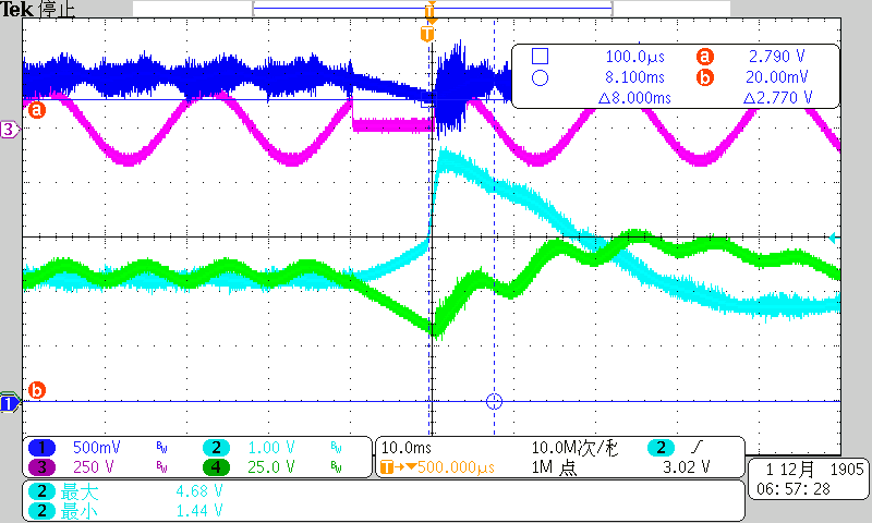
We are conducting a input voltage drop test , with input voltage power off for 10ms and then power on,  when power on, the IC will reach peak current limit and protection for several periods.

This is what we think what happened: as input voltage lost, output voltage begin to decrease, when Vsense is below 2.8V, slew rate correction begin to work, 100uA current source charges VAO,   VAO increases, when input powers on, current loop has a high output  and cause a large duty cycle, then inductor current is charged high to reach the current limit.

Is this right? What can be done to avoid this?

  • Hi Holden Pan,

    Can you check the voltage of the VAO pin to see if it is below 0.75V when the input power is turned back on? UCC28070 has a start-up hold off feature which should prevent the initiation of a soft-start cycle until the VAO pin is below 0.75V and would prevent the inrush current scenario. One option is to externally pull the SS pin low to disable the device when an AC-line dropout is detected. Take a look at section 7.3.14 and 7.3.15 in the datasheet:www.ti.com/.../ucc28070.pdf

    Best Regards,
    Ben Lough
  • Hi Ben,

    Thanks for your reply, when AC power off for 10ms, as there  is large output capacitance, Vsense is 2.7V when AC is back, and VAO is above 2V, see waveform,ch1(Vsense),ch2(Vao),ch3(PFC Vin),ch4(PFC Vout). VAO goes high when AC is back. It's not re-start as Vsense is above 0.75V, and SS also keeps high. I also think when need to pull ss low to disable it.

    Thanks again.

  • Hi Ben,

    Customer wants to use below solution to avoid overcurrent, they add a capacitor and zener diode at IMO, as the capacitor will decrease the slew rate on IMO then make duty cycle change slower, they have tested this circuit and there is no over current when power on and off cycle test. Is this circuit OK, will there be any risks?

    Thanks!

    Holden

  • Hi Holden,

    Because this will affect how quickly the duty cycle can change, I would check that the PFC stage can still meet the customer's transient response requirement. Also check if you are still acheiving sufficient power factor correction.

    Best Regards, 

    Ben Lough

  • Hi Ben,

    Thanks for supporting.

    Best Regards
    Holden