This thread has been locked.

If you have a related question, please click the "Ask a related question" button in the top right corner. The newly created question will be automatically linked to this question.

TPS7A7001: Why used 2pcs devices for this application? Not used 1pcs device.

Part Number: TPS7A7001

Hello Buddy:

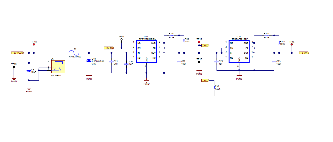
Input 6.5V/2.5A and get 3.3V output voltage.

Why used 2pcs TPS7A7001DDA devices for this application?

Whehter used 1pcs TPS7A7001DDA device for this case by adjustment R1/R2 value?

This device current limit range from 500mA to 2A. Is it right?

  • Hi Simon,

    There are several advantages to place two LDOs in series.  First you have an intermediate rail at 5V.  As I do  not see the entire schematic, I am not sure if the 5V rail is being used anywhere else; however, R90 seems to imply that the 5V rail is going somewhere else.

    Second (and likely part of the decision in this case) you are able to spread the power dissipation.  In your application the total voltage drop is 3.2V.  If you are using the full 2A rated current of TPS7A7001, that would be 6.4W being dissipated which will put a single device in your application in thermal shutdown.  By doing an intermediate 5V rail you are dissipating 3W in the first LDO and 3.4W in the second.  At this point it is important to note that since the junction to ambient thermal resistance is 46.4C/W, you will still likely have thermal issues as the junction temperature of the LDO will be ~140C above the ambient temperature and the maximum operating junction temperature for TPS7A7001 is 125C.

    A third advantage to having an intermediate rail is that you will be able to increase the effective PSRR between the 6.5V rail and the 3.3V rail.

    The minimum current limit for TPS7A7001 is 2.1A:

    Very Respectfully,

    Ryan

  • Dear Ryan:

    Thank you for your excellent explaining!

    And have some questions check with you.

    1. The first LDO 5V be application others place.
    2. I agree your view point about the thermal shutdown consider.

                 A. How to calculate the first LDO power is 3W? the second LDO is 3.4W?

           3.  From the datasheet, LDO min output current is 2.1A. Is it right?

               How to limit output current? or my misunderstand it?

  • Hi Simon,

    You had only stated the supply current limit of 2.5A. Since I do not know the load current for your application, I made (and stated) the assumption that your application would use the full rated current for TPS7A7001. As such I assumed that each TPS7A7001 had 2A flowing through them. Power is equal to voltage multiplied by current; therefore, the power dissipated in the LDO is the voltage difference between Vin and Vout multiplied by the load current.

    For the first LDO: P = (6.5V - 5V) x 2A = 3W

    For the second LDO: P = (5V - 3.3V) x 2A = 3.4W

    If your load current is less than 2A, you can modify the above calculations to fit your application.

    The rated current for TPS7A7001 is 2A. As such TPS7A7001 should only be used in applications where the load current is 2A or less. Current limit is a protection feature for the LDO during fault conditions and is not intended for normal operation. Current limit will engage automatically when the current is above 2.1A. More information can be found in section 7.3.2 Internal Current Limit in the datasheet.

    Very Respectfully,
    Ryan
  • Dear Ryan:

    Copy that!
    Thank you very much!