art Number: TPS63001
Dear TI team and others,
I would like to verify that my board layout using TPS63001 (3.3 V fixed-output buck-boost regulator used with a single-cell Li-ion battery source) is correct.
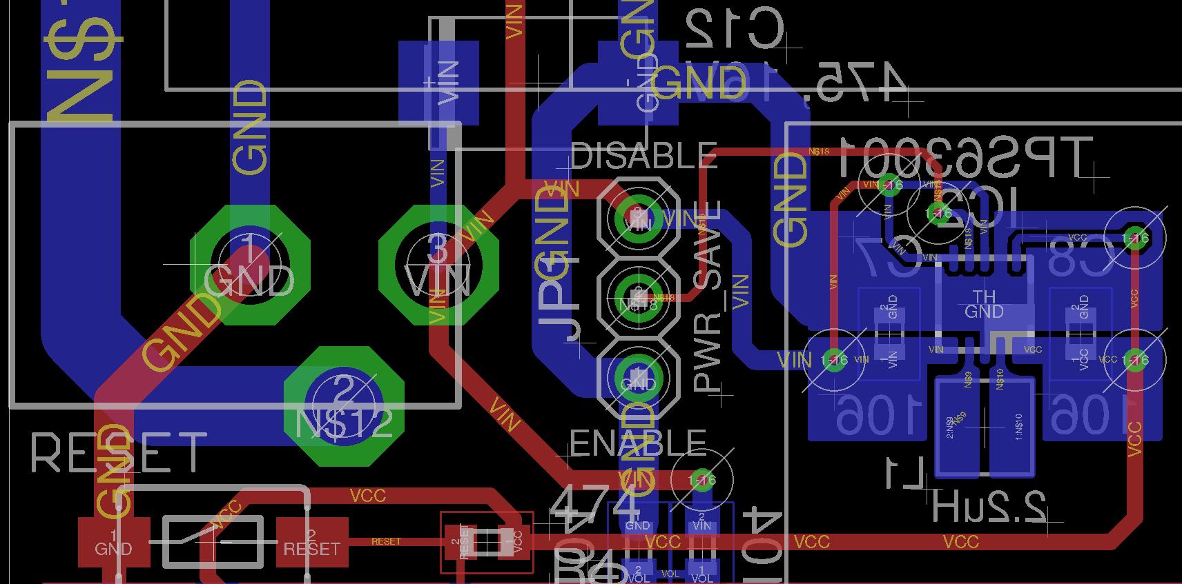
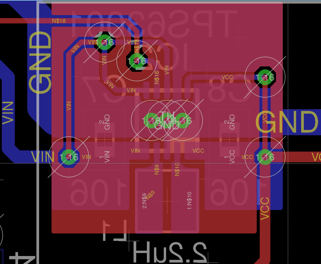
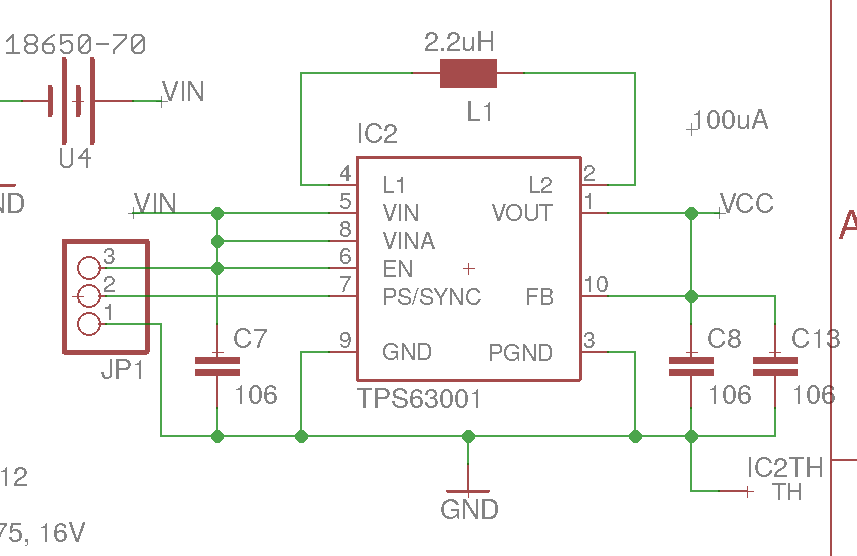
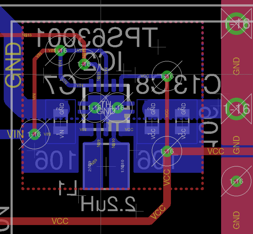
I've attached the schematic and PCB layout as two images as the following. All pins and tracks are labeled. Red tracks are on top layer, blue ones are on bottom layer.
Do you recommend any further changes in general for the overall design before I submit this layout for production?
I'll appreciate any help/recommendation you provided.
Thank you very much.