This thread has been locked.

If you have a related question, please click the "Ask a related question" button in the top right corner. The newly created question will be automatically linked to this question.

UCC28951-Q1: Check my understanding on the usage of 'external' Error Amplifier, and transformer selection for 400V output

Part Number: UCC28951-Q1
Other Parts Discussed in Thread: LM4132-Q1, UCC28951, UCC28950

Hallo E2E,

I am designing an onboard charger, trying to verify if my understanding is correct.

Question 1: External Error Amplifier

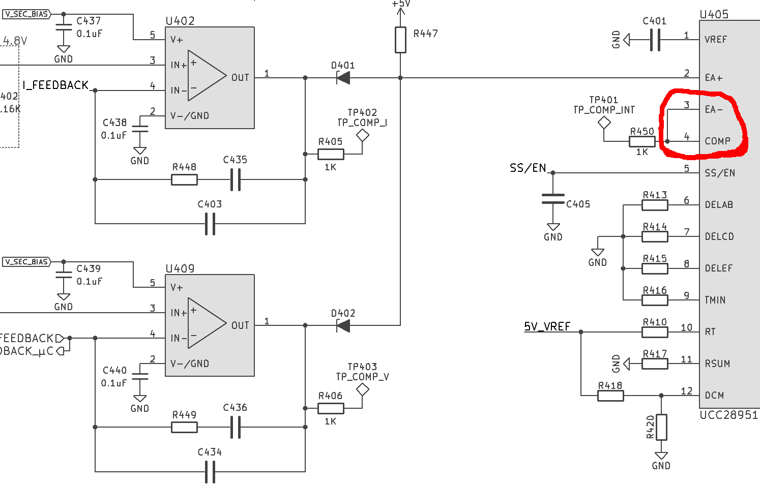
I am sketching an error amplifier part of the circuit and wanted to have automatic CC/CV transitions and had referenced it with the TI training series. When I shorted the EA- and COMP pin makred in red, means that the internal error amplifier will then be "disabled" and whatever sensed on EA+ pin will be use to control the unit, correct?

The TI training series suggested to use LM4132-Q1 as reference voltage source, but the part shows that it can provide the maximum reference voltage up to only 4.1V. Why is the lower Vref was chosen in the TI training series and not some 5V Vref based on what the UCC28951-Q1 provided?

What are the considerations i needed to look for when selecting the value for the zener diodes D401, D402 (e.g. zener voltage, and torlerance)?

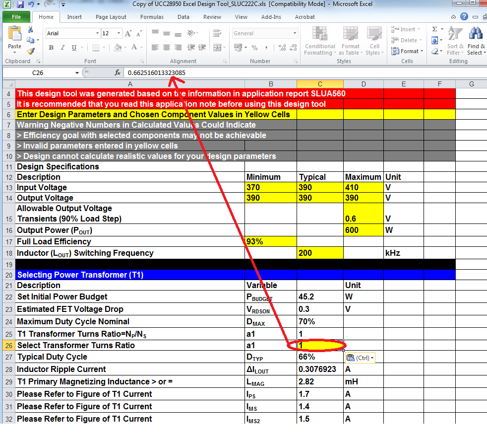
Question 2: Transformer for 400V Operation

I am trying to figured out the transformer specification of the design, and based on the calculation on the datasheet. The transformer turns ratio was calculated to be close to 1 (400V PFC BUS to ~400V output). Is it normal to have this transformer wind at 1:1 ratio?

Is there any design review of such an output voltage operation?

Regards

Natthapol Vanasrivilai

  • Thanks for your interest in TI here. I've contacted the appropriate product group. You should hear from them soon.
  • Hi Natthapol,

    1. The error amplifier is configurated as a voltage follower when you short the EA- to COMP, and the error amplifier output(COMP) will follow EA+. The LM4132-Q1 was selected becasue its precision reference accuracy (0.05%), the internal reference accuracy of UCC28951-Q1 is only 1.5%. For the diodes - them should not be zener diodes but should be general purpose diodes such as MMSD4148T1G. Just for oring the output, the lower outputs of amplifiers turn on its diode and set the demand signal at the EA+ input.

    2. If you are using central-tap in the secondary, you will not able to get the output regulated with 1:1 ratio as the duty cycle would need to be 100%. You should know that is impossible for the converter to operate at 100% duty cycle because the duty cycle lost of PSFB. It is necessary to reserve some margin on duty cycle for the regulation.

    Best Regards
    Oliver
  • Hello Oliver,

    does this mean that it is better to boost the voltage level at the PFC stage to be higher than 400V (to 450V?), then have the UCC28951 runs at lower duty cycle?
    My PFC stage is currently outputting at 400V. What might be the voltage level I should aim for and have enough margin, if the output of DCDC-Stage must be able to deliver a maximum of output voltage of ~400V.

    Best Regards
    Natthapol
  • The most practical way is adjust the turns ratio based on your input voltage range and limit the duty cycle below a specified value according to your power stage, you can use the Power Stage Designer Tool from TI to calculate these value.

  • Hi Natthanapol

    The excel calculator for the UCC28950 rounds the transformer turns to the nearest integer - that works well for a 400Vin / 12V out where the ratio is about 21:1 but the rounding error is significant when Vin = Vout. The Excel calculator shows a ratio of '1:1' but the real value before rounding is actually 0.66:1.

    In the example below, I have set Vin = Vout =400V. Cell C25 shows the transformer turns ratio = 1.  If you copy this cell and paste it into cell C26 it too shows a value of 1 BUT if you click on it the correct value of 0.66... is shown in the arrowed location. All subsequent calculations will then be correct. 

    If however you simple write the value shown in C25 into C26 then the calculator will use '1' in subsequent calculations.

    The truncation should probably have been done to two decimal points but unfortunately it wasn't.

    I hope that this makes sense - the overall point is that yes you can use the UCC28951-Q1 to convert 400V to 400V - probably with a duty cycle of approximately 66%.

    Regards

    Colin

  • exactly this was my problem before. When i use '1' in the calculation, then the whole calculations broke up with bunch of errors. So i hesitated to continue the calculations, and stumbled with confusion.