This thread has been locked.

If you have a related question, please click the "Ask a related question" button in the top right corner. The newly created question will be automatically linked to this question.

BQ24074: ILIM not correct when a load is applied

Part Number: BQ24074
Other Parts Discussed in Thread: BQ24072

I am using the BQ24074 as a single cell Li_ion battery charger, powered from an external USB PSU. I have processor control of the charge enable and EN1/EN2 control lines so am able to set the charge current to any of the available states.

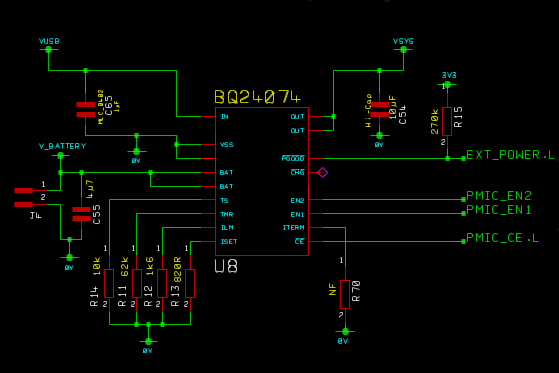
Circuit as follows:

My intentions are:

No thermistor- R14 sets TS to a known good level.

TMR - R11 sets a time I have calculated based on charge current, battery capacity, tolerances plus a bit more to ensure timer is long enough.

ILIM - input current limit from IN (i.e. external PSU). R12 sets this to a nominal 1A (approx. 0.94A min, 1.075A max).

ISET - Max charge current, set to a nominal 1.08A (approx. 0.97A min, 1.19A max).

ITERM - R70 is not fitted so termination current set by BQ device.

I know I have the charge current set to slightly higher than the available input current. This basically makes sure that EVERYTHING is used to charge the battery. In practice there is always a bit used by my processor and other devices but the device will use whatever is left, up to the ILIM input current to charge the battery.

My problem:

I have connected my board to a bench PSU so I can monitor the current. My processor has set PMIC_EN1 to '0' and PMIC_EN2 to '1' which sets the current limit to the value set by ILIM (about 1A). My battery has some charge in (50-60%) and the current drawn from the PSU is about 640mA. This is lower than the 1A I was expecting but I can be persuaded that this is due to the state of the battery (??).

However, when I add additional load onto VSYS (i.e. another 200mA) I would expect to see this additional current being drawn from the input PSU as I am still well under my current limit set by ILIM. Instead I don't see ANY additional current being drawn from the input voltage and instead see the extra current being supplied by the battery. I would expect this behaviour if I had reached the ILIM value but not while I am well under it.

On a previous prototype version of this board I had used the BQ24072 (same device family, slightly different options, all resistor value were the same) and this did operate as I would have expected.

So in short, why is the BQ24074 not behaving correctly. It looks like it is current limiting far too early and not at the design level. I have checked the values fitted to the PCB and they are as specified.

Any help appreciated.

  • Hello,
    Please post scope shots showing the Input and charging current as well as VIn and VBAT.
    -Raheem

  • I have taken a few scope traces as shown below:

    I have been unable to capture all the data at the same time so in each graph I have followed the same test procedure.

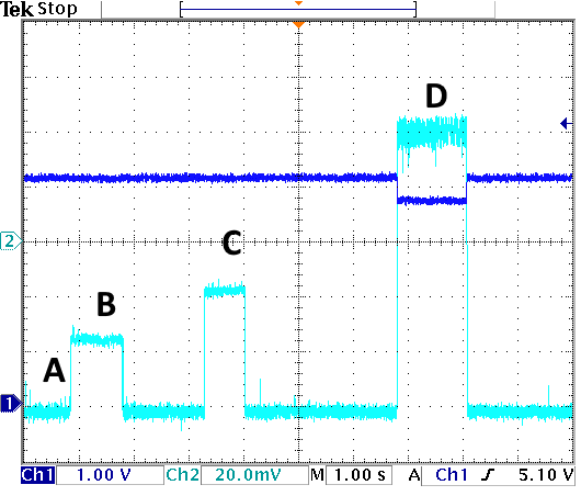
    Figure 1: Battery current and BQ output voltage. Blue = BQ Vout , Turquoise = Battery charge current (100mV/A)

    The above results are whilst charging a battery AND applying additional loads onto the BQ output.

    Marker Vout I Bat
    A 4.18V -616mA
    B 4.18V -364mA
    C 4.18V -184mA
    D 3.68V +420mA

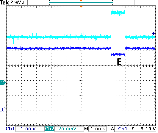
    Figure 2: BQ Input current and BQ output voltage: Blue = BQ Vout , Turquoise = BQ Input current (100mV/A)

    The 3 different loads were still applied in this test but the first 2 made no difference the input current of the BQ device or its output voltage.

    Marker Vout I in
    E 3.68 932mA

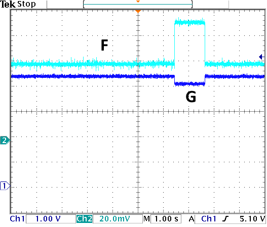
    Figure 3: BQ input voltage and BQ input current

    The 3 different loads were still applied in this test but the first 2 made no difference the input current of the BQ device or its input voltage.

    Marker Vin I In
    F 4.32V 604mA
    G 4.04V 940mA

    Observations

    The BQ device seems to limit the input current at approx. 610mA. When additional loads are applied it reduces the charge current to the battery in order to supply the extra current to the Vout output. Only when a very large additional load is applied does it stop charging the battery and change its input current limit to the one I have actually set (i.e. about 1A). At this point it is using current from both the input source and battery in order to support the VOUT voltage.

    I believe this is different behaviour as specified in the datasheet, figure 20. I don't think my device is working correctly in the DPPM Loop Active mode.

    Thank you.

  • Additional info - the unloaded battery voltage for these tests is approx 3.95V.
  • Additional info - I have also tried changing R13 (ISET charge current resistor) in my circuit to 1k1. This will reduce the max charge current to 895mA which is under the worst case min input current limit set by ILIM (928mA min limit). I tried this in case the BQ was getting upset about having the battery charge limit higher than the input current limit.

    Result - made no difference.
  • Nick,
    Looking at figure 1 and 2, you show Vout at 4.18V and 3.68V. This surprises me since Vout in the BQ24074 is regulated to 4.4V. I think that is supposed to be VBAT since the voltage decreases with more current discharge. Also in figure 2, you have VIN = 4.32V and 4.04V which is below the V(IN-DPM) voltage of 4.5V. If the input voltage is below 4.5V, the IC will reduce the input current which is probably why the input current you see is lower than expected.
    Regards,
    Raheem
  • Hi Raheem,

    I think you have solved it! Where USB/DC power enters the circuit there is obviously the USB connector as well as a series Ferrite bead (0.05R max) so I would expect a small amount of volt drop across these components. However....to make testing convenient for me I was using a long (and quite thin) USB lead - this lead had a resistance of approx 0.83R which caused sufficient drop to create my problem.

    When I changed to the USB lead that actually ships with the product (0.25R) the problem went away and charge currents were as I expected.

    Therefore, as you suggest, the voltage seen at the input of the BQ chip being too low was causing it to reduce the input current.

    Thank you for your help.

    Nick