This thread has been locked.

If you have a related question, please click the "Ask a related question" button in the top right corner. The newly created question will be automatically linked to this question.

LM5045: LM5045 issue

Part Number: LM5045

Hello,

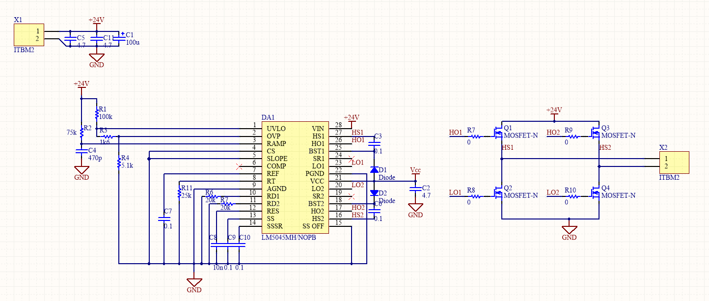
we tried to make working a very simple circuit based on an LM5045, but the device does not want to run.

We built three boards, and always the same behavior, however, all signals are good..

Could you check this schematic and tell me if something is wrong please...

MOSFETs and parts are more or less the same than as your evaluation board.

Thank you in advance.

  • Hi Fabrice,

    I can take a look at your shematic. Could you try reposting it to this thread? I don't think it made it into your original post. Also can you describe what is the behavior you are seeing?

    Best Regards,
    Ben Lough
  • Hi Ben,

    Thank you, here is the schematic :

    The behavior is simple : nothing appends, all signal are good (Ref, Vcc, Ramp, OVP, UVLO, etc) we supply the board with 24VDC, and no current consumed... It looks like the device to be in standby mode.

    Best regards.

  • Hi Fabrice,

    It looks like the current sense pin is grounded. Can you confirm? Could you show where your current sense transformer is? Also it looks like the COMP pin is floating. Is your feedback network connected?

    Best Regards,
    Ben Lough
  • Hi Ben,

    Yes the CS pin is grounded, and the COMP pin is floating, there no current sensing circuit, and no feedback network, we do not want to use these features...

    We want to use it as simple H bridge controller in voltage mode.

    Best regards,

    Guillaume Dumas

  • Hi Guillaume,

    The controller is wired properly to me. But note that since you don't have external bias supply/aux winding, the VCC is constantly powered by the internal LDO. The FET of the LDO experiences a large voltage drop of 24V-7.8V. Even a small amount of extended ICC could cause overheat of the internal LDO which in turn triggers the internal OTP.

    The LDO is basically a startup regulator. It is typically recommended that an external bias supply or aux winding be used to supply the VCC after the start up of the chip. Please supply an external voltage (>8V) to VCC to bypass the internal LDO. Let us know if it addresses the issue.

    Regards,
    Wangxin