Other Parts Discussed in Thread: CSD19537Q3
Tool/software: WEBENCH® Design Tools
Hi,
We are using the TPS40210 for generating the 48V phantom voltage for one of our application. We have simulated same in WEBENCH and followed the refference design with some slight modifications in the component selection. The WEBENCH simulation report is also attached here.
webench_design_3656248_20_312178119.pdf
The current schematic of our design is same as that of below image
Initially when we test the board with no load condition by gradually increasing the input voltage from 6V to 12V the regulator was working fine and we could see the 48V at the output also.. But when we give a steady 12V input the output voltage drops suddenly to around 10V and after a few seconds we could see smoke from the board, when we inspected the board it seems the MOSFET is damaged.all this testings were done with no load condition only.
The main two difference between the simulation and our actual design was the MOSFET and Diode selection. Since our board the max load current can be around mA from the48V we thought a MOSFET with Id of 1A will be sufficient enough as the switching current is seems to be around 500mA only for the 60mA load current.
But all our testing was in no load conditions only and even in no load condition also the MOSFET is damaged..
Now we changed the MOSFET to the same part as that of the TI WEBENCH simulation report and CSD19537Q3 is soldered to the board with little rework to replace the initial BSH114 MOSFET. Still then we saw smoke when we start the regulator by gradually increasing the input volatge. This time when the input voltage was 5V, the current in the power supply increases to 1A and we could see smoke coming from the MOSFET area of the board..
Can any other have the such an issue of damaging the MOSFET even in no load condition..?
We have followed the all the design recommendations and tried to follow the WEBENCH design as close as possible.. what may be the possible reasons for the MOSFET damage..?
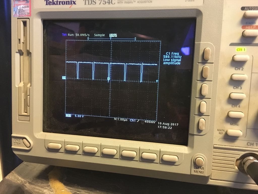
We checked the gate drive waveform and is seems to be more or less close to the simulation report ie. 580KHz at 86% dutycycle..scope waveform is also given below


