This thread has been locked.

If you have a related question, please click the "Ask a related question" button in the top right corner. The newly created question will be automatically linked to this question.

BQ24192: BQ24192 RT1 and RT2 calculation

Part Number: BQ24192

Hi,

I am planning to use bq24192 charger chip in my design.

Few queries:

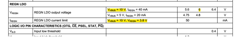
  1. What will be the output Voltage level of the REGN pin @ VBUS=5V?On Datasheet page # 9, There are two different voltages, VREG=6V @ VBUS=10V and in IREG measurement, VREG = 3.8V & VBUS=10V. Is REGN programmable? See attached image Highlighted with yellow color.   
  2. I found that the RT1 and RT2 value is calculated for 0 to 45C Li-ion battery. Refer datasheet section 9.3.3.4.1 page# 21. How to calculate RT1 and RT2 values for -40 to 85C temp range battery?
  3. How to scale the VLTF and VHTF voltage levels against the required charge cycle temperature window shown in Datasheet Figure 16, page# 20?  i.e, What is the value of Cold temp threshold in °C in given example & how to derive from/scale with VLTF?

Thanks,

Ritesh

  • Ritesh,

    1. The REGN is typical 4.8V @VBUS=5V and the IREGN=20mA as shown by the second line of the VREGN spec. The line of VBUS =10V, VREGN=3.8V means the REGN current capability - no less than 50mA can be drawn from the REGN when the REGN is overloaded and drops to 3.8V.
    2. The 0 to 45C is the temperature range that battery is allowed to be charged, not the bq24192 operating free-air temperature range which is -40C to 85C as shown on the datasheet page 6. Please check the battery charging specification to ensure the charging safety.
    3. The VLTF/VREGN is the percentage value as shown on the datasheet Page 8. The calculation example is on the datasheet page 21. The calculation tool can be found here: www.ti.com/.../technicaldocuments.

    Regards,

    Eric