Hi,
I am currently designing a power supply system based on a TPS5430. This power supply will deliver energy to a device that is around 1 meter away from the designed PSU, and I would like to use the VSENSE pin/ feedback feature as a line loss compensation system.
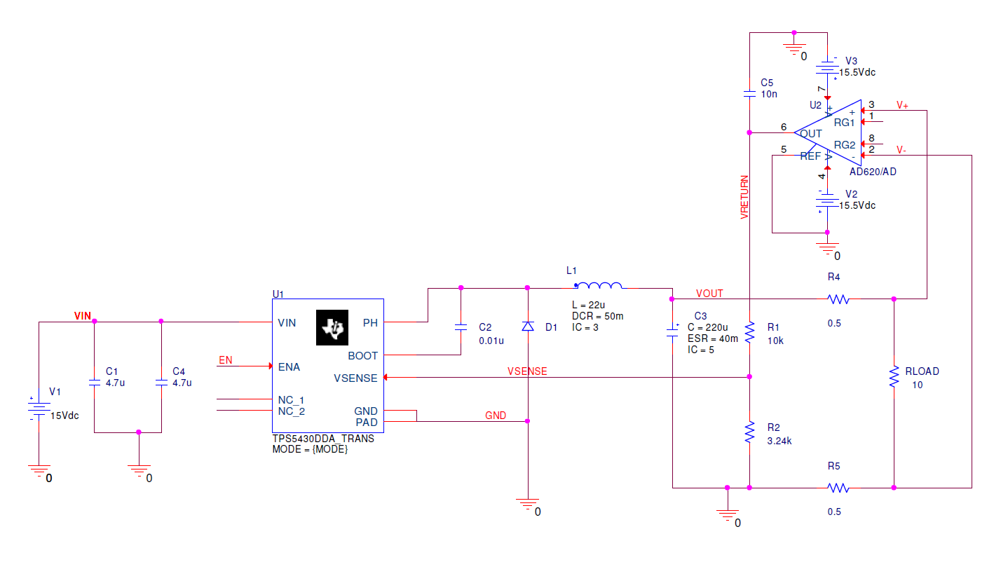
Please find attached the design I came out with.
This design has been made from the Pspice steady state simulation model of the TPS5430.
The input of the feedback voltage divider is connected to the output of an instrumentation amplifier. The two inputs of the amplifier are connected to the load, to sense voltage between its leads.
Two additional resistors have been added on each pin of the load to act as a (very) simplified model for wires.
If R4 and R5 values are below 0.5ohm, simulation works, and the DC/DC output is regulated (with an offset though…).
If those resistors have a value above 0.5ohm, the output oscillates then goes to 0v.
I am unable to tell if this behaviour is because of the simulation profile, or the design itself.
Datasheet says that VSENSE pin must stay between -0.3V and 3V. In any case, I am way above the lower limit. Is there a treshold above which the converter stops oscillating ?
Please find attached waveforms. The one that works is with R4=R5=0.5ohm, the one that doesnt (VOUT=0v) is with R4=R5=0.6ohm.
Any input would be appreciated, thanks in advance.
Best regards,
Adrian Gascoin