This thread has been locked.

If you have a related question, please click the "Ask a related question" button in the top right corner. The newly created question will be automatically linked to this question.

The output resistance of TPS65023

Other Parts Discussed in Thread: TPS65023

I have designed a PCB barod according with the schematics in Datasheet of TPS65023;  Now, I find  the resistance of every output is below 50 ou(resistance between Lx and PGND) and the input current of the chip rises to 1.17A  immediately when the out power switch puts on and the output load of TPS 65023 is nothing . Meanwhile,the temperature of TPS 65023 grows to a level that we can not accept and it will be demaged if we could not turn it off from the elecrocircuit in threes seconds!

I feel  perplexed that  the output resistance is so small while the datasheet anounced it's  huge (About 1M ou)? 

I am sorry for my poor English  if there is some information  I have missed or give some uncorrect statement!

Finally, Thank you very much for any reply from you !

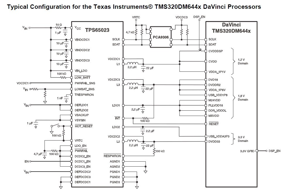
The shemetics in  my electronicircuit

  • Are you saying you measure 50 ohms from Lx to ground?  This value seems very low and could be the problem in your circuit.  Does this problem happen on all your boards or just one?  Can you remove the TPS65023 IC and measure the resistanc to see if the problem is a damaged IC or maybe a problem with layout or with the DSP?  There is no known problem with the TPS65023, so let's concentrate on debugging potential places where the 50ohm short can be.  Can you also confirm that your inductors and capacitors meet the requirements in the datasheet.

  • Have you been able to resolve this problem?  If so, can you tell me the root cause?

  • No further responses from customer, so we'll assume one of the original suggestions led them to the answer.

  • Well, I feel so sorry for I havn't give the responses immediately to you  about  the solution of the problem that the risistence between Lx and GND of TPS 65023 is quite low because I couldn't visit your website in Chinernet (Internet in China which is regulated strickly by the authority who always do something to make some obstacle in technoladge or untecholadge to stop the people in China visiting the website aboard)
     
    As your engnieer said, the IC was damaged immediately before we took any effective action to avoid the situation happaned ,and then we found the risistence、the input current is quite high,absolutely it's unnormal. We have measured the risistence between Lx and GND of a new IC whose value is just the Datasheet anounced while the damaged one is below 50 ohm. And we damaged another two chips to find this problem.Finally , the problem is the inductor. The inductor we used is a SMD piezoelectric ceramics instead the winding ones. When we tried to change the inductor, anything unnormal is disappeared and we haven't found the explain in theory!