This thread has been locked.

If you have a related question, please click the "Ask a related question" button in the top right corner. The newly created question will be automatically linked to this question.

BQ76920EVM: The Board i am trying to set up for 3 cells ( Picture attached) , DCHG FET is toggling not enabled continuously ?

Part Number: BQ76920EVM
Other Parts Discussed in Thread: BQ76920, BQ76200, BQ78350-R1

I am using BQ76920 EVM board for 3 Cell BMS i have connected cells like -

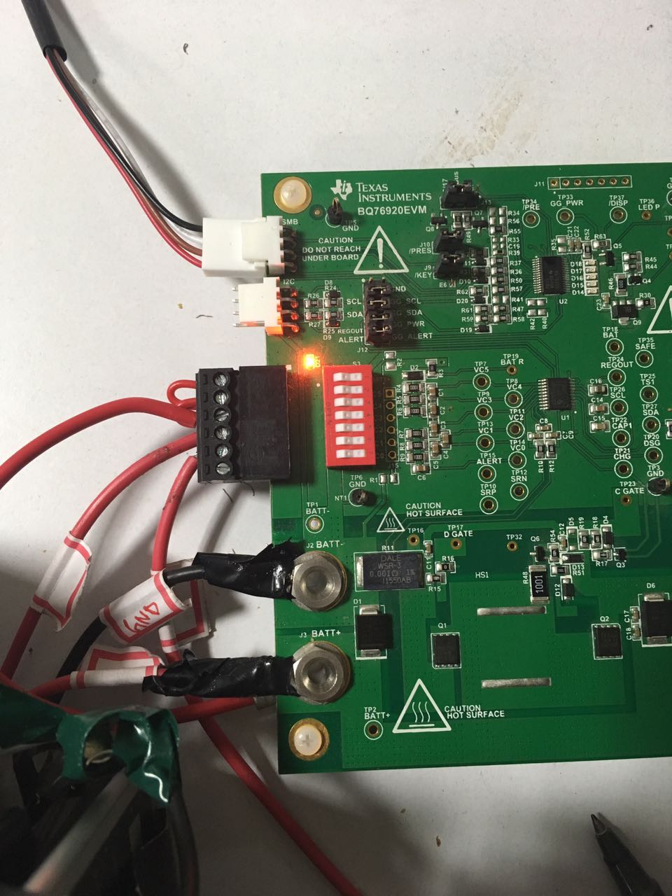
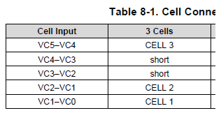
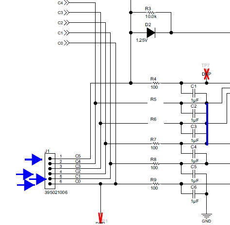
1.I have shorted the VC3-VC4  and also VC4-VC5 can be seen in the figure .

2.I have set the AFE Cell Map to the Cell 1 ,Cell2 and Cell3 

3. I have calibrated everything the voltage and current .

4. Now i an trying to discharge the load but the FET Enable button just toggles the load not let it get connected continuously ?

Even i have tried FET toggle it also shows some dis continuous behavior,

THE RED ZONE IS WHERE FET TOGGLE IS PRESSED .... REST IN THE STARTING FET ENABLE WAS USED .

Please Help .

  • Hi Ram,
    In the picture there are connections to the cell input connector and power connection which looks like cells may be used, but the LED is on. The LED indicates that the voltage divider resistors are used for cell simulation on the board, these will discharge cells.
    The top cell should be used on the bq76920. See the EVM user guide section 6.3. With cells the top of the cell stack should connect to BATT+ to deliver current, but also to the cell input connector for sensing and to power the electronics.
    You may find it easier to connect to a power supply and use the the resistor divider on the board to set up the system parameters. The gauge experts will have better advice.
  • Thanks a lot for the help ..!!

    Everything Working fine for me now :)

    Here it the new circuit connections......

    Please Confirm i am doing everything good --

    1.I removed 2 resistances R4 and R5 .

    2.I have also turned off the simulator.

    3.I have given Power Supply to the Top most Pin .

    Its working now ... suggest any more changes if you found necessary ??Thanks a lot

  • Hi Ram,

    It is good that it is functioning, but the configuration is not what is recommended for best performance.  It appears R4 and R5 are removed which would use the bottom 3 cells of the IC.  The wire from the cells to BATT+ provides the high current through the board, the wire from BATT+ to terminal block C5 provides power to operate the bq76920, the wire from C5 to C3 provides monitoring voltage for the top cell through the filter to VC3.

    With 3 cells it is recommended that the 5th cell input of the IC be used to monitor the 3rd cell of the battery.  This is shown in the bq76200 datasheet table 8-1:

    The filter on the EVM is recommended to be modified as shown in table 3 of the EVM user guide :

    If you remove the resistors your wire on the terminal block from C5 to C3 is not needed since R6 would be removed.  The AFE Cell map for the bq78350-R1 would be 0x0013. 

    The EVM input configuration would appear: