This thread has been locked.

If you have a related question, please click the "Ask a related question" button in the top right corner. The newly created question will be automatically linked to this question.

LM5170-Q1: for CCCV charging module 54.6V 30A max (12S LiPo)

Part Number: LM5170-Q1
Other Parts Discussed in Thread: LM5170, TIDA-01168, PMP4333

Hello,

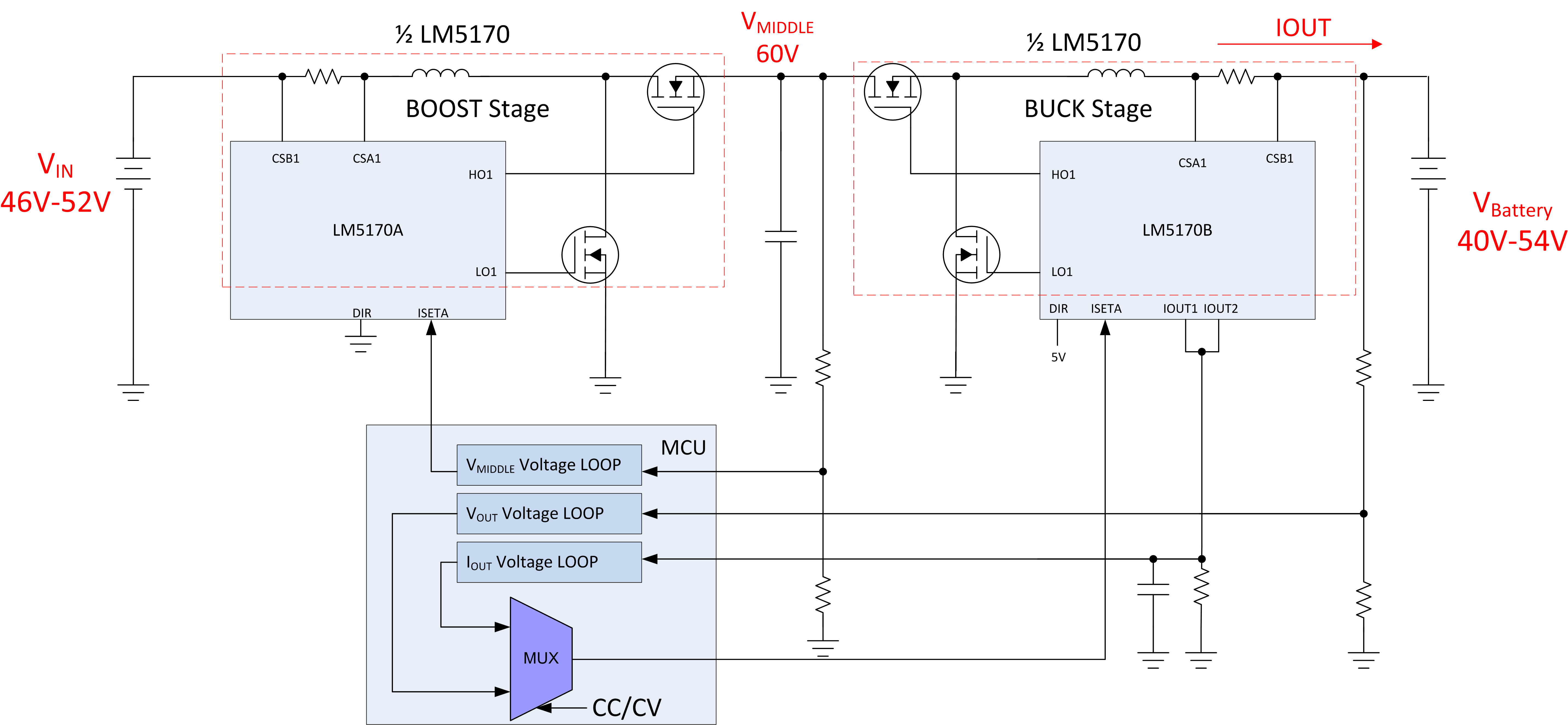
Can I use this IS for creating 12S LiPo rapid charger with two operating modes:

- constant current from 12 to 30A set by MCU

- constant voltage from 40 to 54.6V set by MCU

Module should be powered by external 46-52V source (up to 60A available).

Preferably, buck-boost converter.

Please direct me on useful recourses with reference schematics with LM5170-Q1 in mind.

If this IC is unsuitable, can you recommend good alternative starting point?

We usually worked with 6S packs (24V) and options are widely available for that but switch to 12S looks like creates serious lack of useful info on web...

Thsank you

  • Hi Sergey,

    Thanks for reaching out to us. For higher power designs the LM5170 IC is a good choice. For this application I think the best way to achieve regulation when VIN is equal to VOUT is going to be cascading two LM5170 making a buck-boost converter. The cascaded convert is need due to the LM5170 being a buck or boost converter depending on the setting of the DIR pin. Please see the below block diagram. 

    The IOUT1 and IOUT 2 pins can be used to monitor the charge current. The middle voltage would be regulated all the time with one control loop.  

    I have a few questions.

    1. Do you need Bi-direction functionality? Or are is the battery just being charged?

    2. What is the peak power level of application?

    Please take a look at the idea and let me know if you have any questions.

    Thanks,

    Garrett

  • Garrett,
    Thank you very much to your prompt and professional response.

    1. Module is one direction only . It is for automatic charging of smart batteries (with built in active balancing).
    2. Peak power is required during constant current mode and equals to 1700W including losses on a way to LiPo cells.
    3. I think we need to parallel 2-4 power mosfets to make modules more reliable. Is that possible with LM5170?

    4. Practically, we can step down to 24V input voltage, then we do not need first boost cascade but I worry about overall efficiency in converting 24V to 54.6V at required power level.

    5. Can we force 1/2 LM5170 (or second one) to work in group and control parallel Buck cascade(s) to decrease load on inductors and MOSFETs?

    Any help is appreciated
    S
  • Garrett,
    I have checked datasheet once again, I worry LM5170 has just one ISETA input and hence cannot control two independent cascades... Please advise
    Regards,
    Sergey
  • Hi Sergey,

    This cascaded topology will need to utilize two LM5170 ICs. This means that there will be two phases boosting and two phases bucking. Which for the peak power is probably desirable. Other LM5170 ICs can be added to increase the number o phases, which will help to reduce the physical size of the components in each phase.

    The LM5170 is capable of driving multiple MOSFETs. This is due to the internal 5A gate drivers.

    What is the total efficiency target that your design will require? This can be greatly increased by component selection and layout.

    Thanks,

    Garrett
  • Garret,
    I have done some calculations for LM5170 on weekend and looks like best option for me is to focus on the next two options:

    1. Non-isolated solution based on LM5170 (less components than via two stage converter)
    - input 28V (20 - 34V) from custom 8S (3.6V) LiPo power bank
    - 20A output max, 36 - 50.4V range

    Questions are:
    - how to estimate ripple voltage/current @ output considering TIDA-01168 circuit. I need to estimate output error because for charging LiPo pack I need to be sure to switch to constant voltage at exactly 4.2V per cell, not exceeding it during charge for more than 25mV
    - in connection for question above - any chance to reduce number of Al Polymer capacitors @ output and input? Looks like they are very costly - about 30% of total cost of the module!
    - how stable LM5170 in DCM? Looks like I cannot avoid this mode because charging cut-off should be done at 0.03C or 0.6A, that is far from CCM region

    2. Isolated Flyback solution. For instance like PMP4333.
    - input 48V
    - 20A output max, 36 - 50.4V range

    Questions:
    - can you give me good starting point for about 1kW MCU controlled constant current/constant voltage isolated solution?
    - can it be done in 2-3 phase to distribute heat even, to reduce height of the module and eliminate costly and rare high current transformers/inductors.

    Thank you in advance.
  • Hi Sergey,

    My comments are below.

    Questions: Option 1

    - how to estimate ripple voltage/current @ output considering TIDA-01168 circuit. I need to estimate output error because for charging LiPo pack I need to be sure to switch to constant voltage at exactly 4.2V per cell, not exceeding it during charge for more than 25mV

    Output voltage and current ripple can be calculated like any buck converter for the side of the low voltage terminal and like any boost converter for the high voltage terminal.To get this kind or accuracy you will need to have a very accurate reference for the outer voltage loop control. Adding extra output capacitance will also help reduce the output ripple.


    - in connection for question above - any chance to reduce number of Al Polymer capacitors @ output and input? Looks like they are very costly - about 30% of total cost of the module!

    This could be reduced but it depends on the application. It would also be possible to replace these capacitors with a lower cost capacitor.


    - how stable LM5170 in DCM? Looks like I cannot avoid this mode because charging cut-off should be done at 0.03C or 0.6A, that is far from CCM region

    In DCM the converter should be stable. Since the control scheme is average current mode control the DCM operation performance should be an improvement when compared to peak current mode control.


    Questions: Option 2

    I don't support these devices and am not the best resource to answer this question. Let me find the owner of these ICs to help answer these questions.


    Please let us know if you need anything else.


    Thanks,


    Garrett