This thread has been locked.

If you have a related question, please click the "Ask a related question" button in the top right corner. The newly created question will be automatically linked to this question.

TPS40170: TPS40170 Startup Overcurrent

Part Number: TPS40170

I would appreciate some advise on the soft startup and avoiding over current tripping the startup.

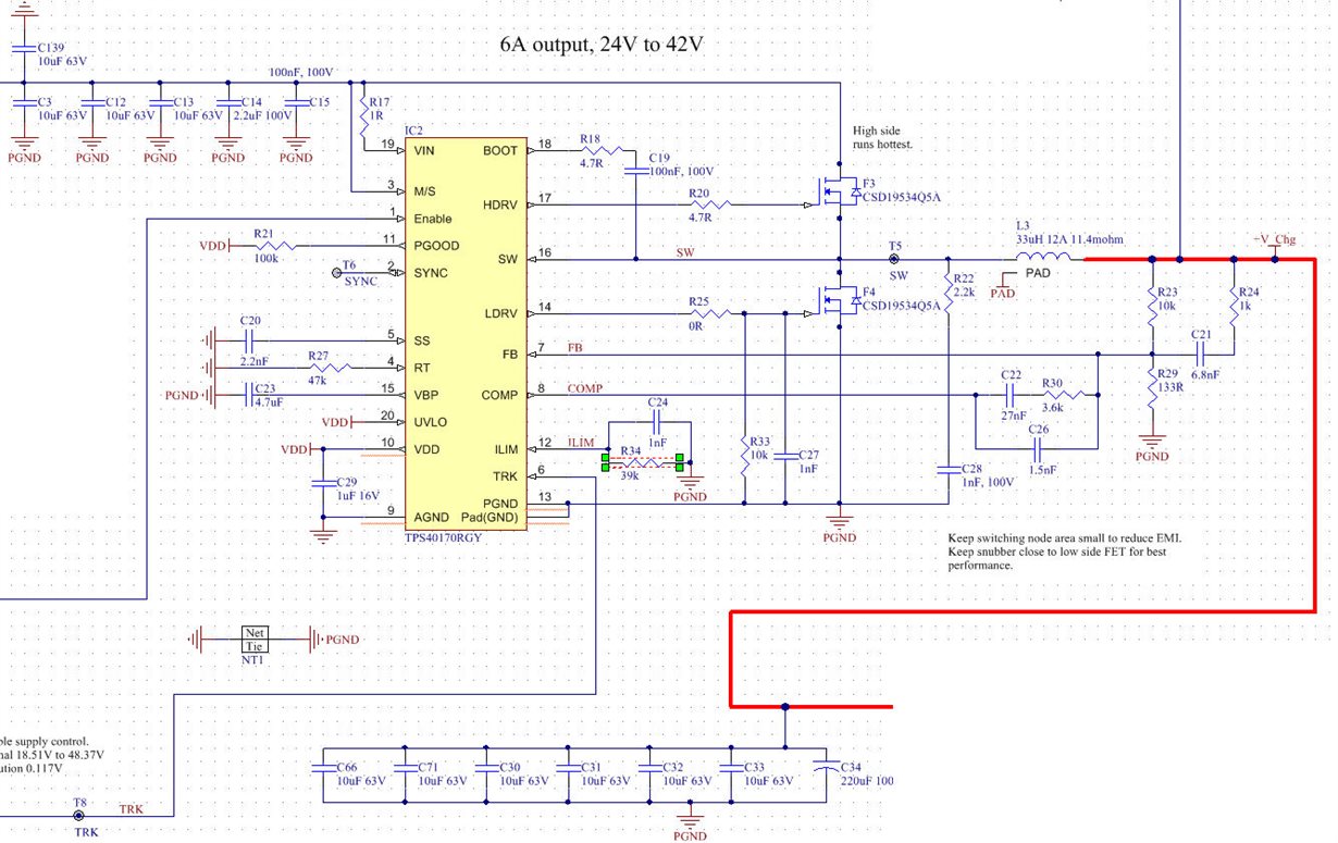
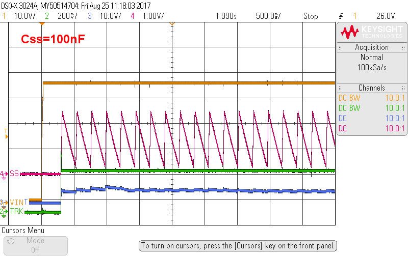
Webench recommends and Rlim=39k and Css=2.2nF, however the startup time is very short and buzzing the capacitors with repetitive inrush current re-starts.  I want to target at least 100nF for Css, however the regulator will not start even at 10nF.  It will start at 2.2nF, however without a load connected.  100mA load will prevent startup.

Scoping with 200MHz probe/BW and probe ring local grounded, the SW node and both gates are very clean, <1V ringing.  VIN, VBP, VDD, TRK all stable and no notable noise during startup.  Enable goes high when input is already stable at 48V.  Once started, it runs >94% efficiency with 48V input, with 19V output/5A load.

I would like to achieve a softer startup, capable of startup with load. Would appreciate some input!

  • Hi,

    Does the converter only hitting current limit during soft start? Seems like on the first scope capture, the soft-start still start and discharge even after the output is reached? Also, do you have inductor current waveform available?
    I would think if you prolong the soft-start (increasing the soft-start capacitor), you will not hitting current limit.

    Thanks
    -Arief
  • I don't have a current probe unfortunately. I can tell the current is chopping, as the capacitors are very audible.

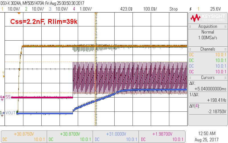
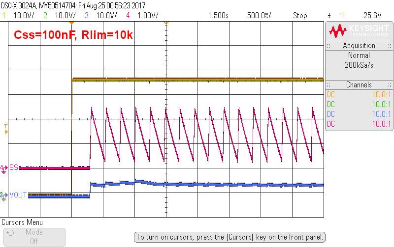
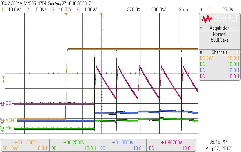
    In both examples, the output fails to reach the target output voltage and the restart persists indefinitely. When I do get the regulator started, it performs very well, low noise and stable through to 5A load tested. Increasing the soft start time causes the issue to be worse and the output voltage reduces (longer restart time). The only way I can get the regulator started is with a very short start time (high current). Even then, a 100mA load will prevent the startup.
  • Some additional information...

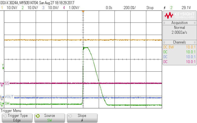
    The first scope trace shows a startup taking 600ms and reaching the target voltage, using a Css=2.2nF.  This is the Webench recommended capacitor, however this calculates to be 0.2ms startup.  The nominal time specified in the datasheet is 4ms.

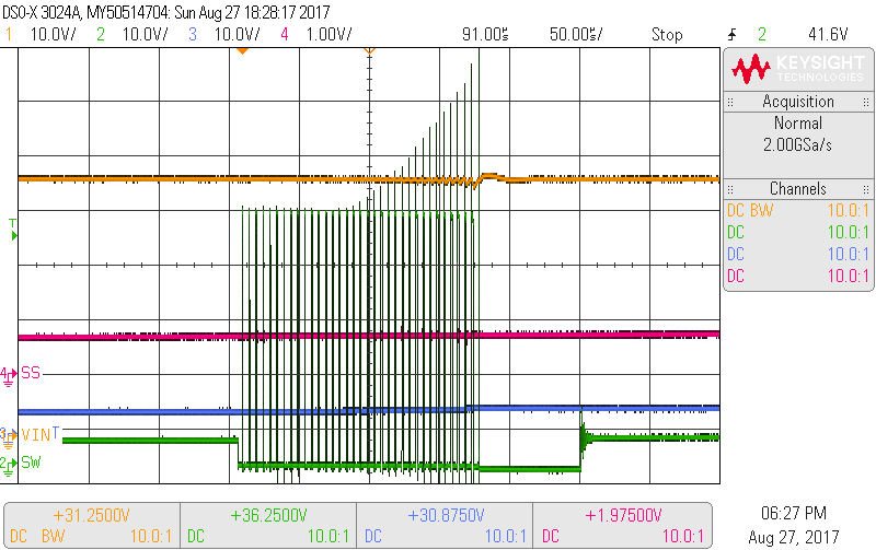
    The second scope trace shows the startup failing (500ms/div), using a Css=100nF.  It should take 9ms.  It does not reach the target voltage.

    These captures were taken using a different PCB sample.

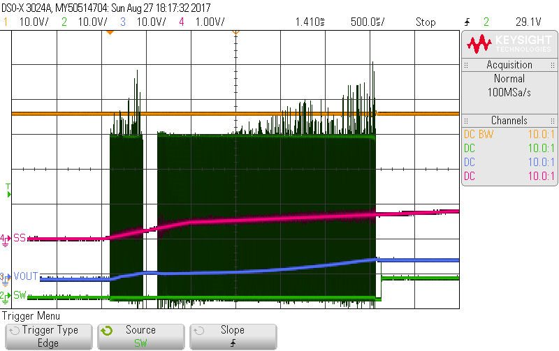
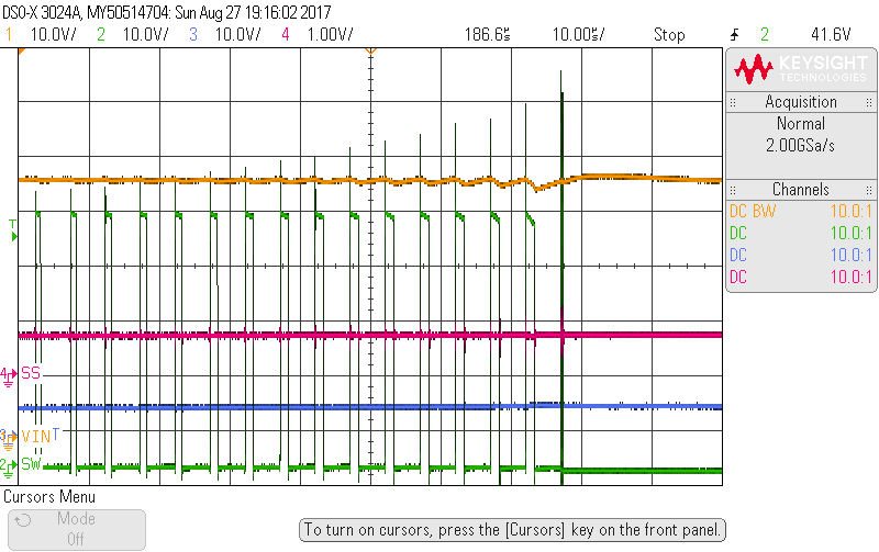
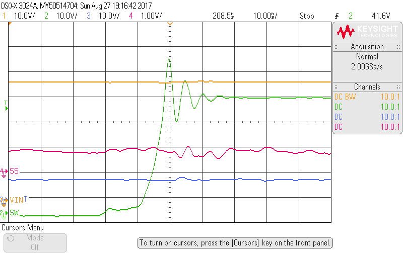
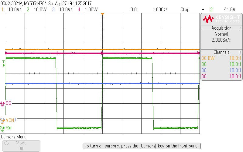
  • These additional scope captures show detail for the SW node.  The probe did not have BW limiting and was measured with ground at the probe ring tip.  Each successive capture is zooming in on the green SW node signal.

  • What I have observed during the startup, is an increasing amount of ringing at the switch node.

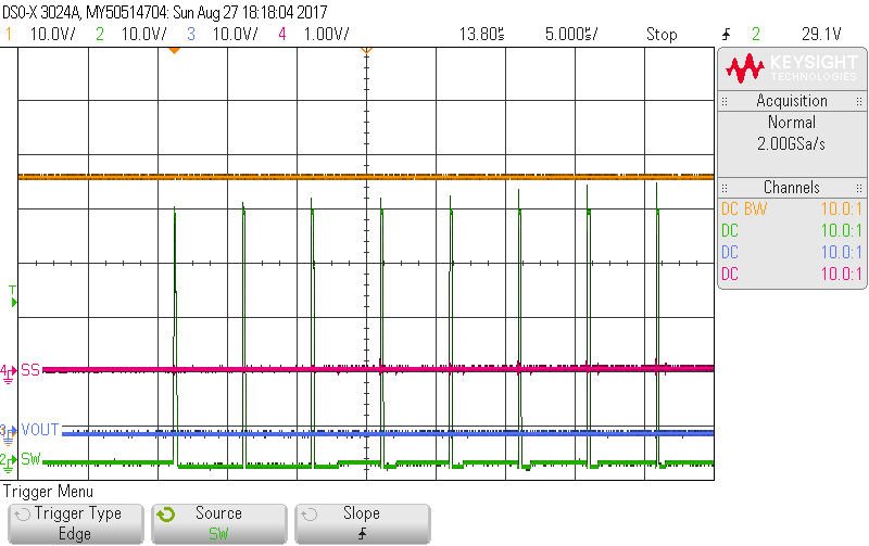
    During normal running, the switch node has no excessive ringing, as shown below.  

    I hadn't needed a snubber at the switch node previously, however I have introduced a 330pF 4.7R snubber.  The regulator is starting up, but only if the output is already below <1V before enabling.  If the output capacitors are still discharging and the voltage is greater than ~1V, the regulator hiccups indefinitely on startup.

    Closer to solving this issue and could probably implement a bleeder resistors/software workaround, however I do not have an understanding of why the switching noise occurs during this particular scenario.  Would greatly appreciate some input and advise.

  • I think the switching noise is also dependent upon layout. Make sure that your input capacitor is close to the two mosfet that you have on the schematic.
    www.ti.com/.../slpa005.pdf

    You can try to place the input capacitor close to the MOSFET as the article indicates

    Thanks
    -Arief
  • Thanks Arief.  The input capacitors are right next to the MOSFETs.  The layout is quite good and even benefits from 2oz copper on external layers.  Please note how good the switching waveform is in the last picture.  This is normal running operation.  It is only during startup where this switching noise is detected.  This noise is also inconsistent, increasing with duration.

  • Can you clarify the operating condition? Is the 24V to 42V note on the schematic for the input voltage range? What is the output voltage? The resistor divider 10k and 133R will give you about 45V output voltage.

    The output capacitors are not shown on the schematic. How much capacitance is there at the output, including at the input port of the load?
  • Also, 


    Please check the following.


    • Are you using an input filter?  or are the long cables to the supply.  If there is any instability on the input supply due to LC ringing, this will cause the device to ring and hit ILIMIT.  

    • This Can be remedied by placing a large value electrolytic on the input side using a relatively high ESR to dampen the input supply LC ringing.

    • Regarding the layout, make sure you have routed the Vin and Vsw to their respective pins on the TPS40170 differential.  If you have not, unfortunately you run the risk of parasitic inductance in the measurement loop and will hit ILIM prematurely.


    If you resolve both issues above, the Ilimit should behave well.


    PS: both slowing the Switch node and placing RC snubber have shown to provide some benefits, but may not completely resolve the issue if 1 and 2 are not taken care of.


    Hope this helps?


    Kind regards,


    David.

  • Thanks David!

    The input is 48V. The output voltage is controlled by a digital resistor, between 24 to 42V. I have run this design with only a resistor divider to isolate testing.

    The output capacitors are shown on the schematic. Follow the red wire. Depending on the state of the system, there is an active diode connected to the output that connects to a further ~1500uF.

    The input has a PI filter. 20uF, 2.2uH, PFET for reverse bias and then to regulator input capacitors. Recently, I have been running with an additional 220uF electrolytic on the input capacitor side, as the ceramics were audible at higher load currents.

    The cable is ~70cm 1.85mm2 to a lab power supply. 48V 3A. I haven’t noticed any ringing of significance on the power supply input. I have previously connected a 220uF electrolytic to the cable input.

    Vsw is 2.4mm from the FET. Vin has 2 vias before getting to pin 19.

    Having a pre-bias voltage on the output seems to be the only unusual issue, as this regulator is supported to specifically support this. However it appears sensitive to this level given the test results.
  • Regarding the Input filter, there may be a certain point during start up that it oscillates, remember Rin (Vin/Iin) of your converter in much lower at a low vin, if the part is soft starting while Vin is rising? Zout(filter)<Rin. During Start up , Vin is potentially low, with Vin rising (if not Enabled after Vin stablized) and/or Inrush current to Cout due to a fast DV/DT will also cause Rin to be even lower during this dynamic event. its during this start up period there could be instability that is unnoticed in steady state conditions, as you mentioned you did not see any instability. Please jut make sure that you have enough ESR on your Cin Electrolytic. A quick test is to physically put 1ohm in serious with the 220uF, just to make sure and retest?

    Hope this helps?

    David.

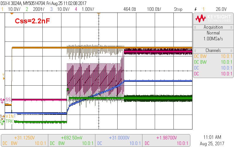
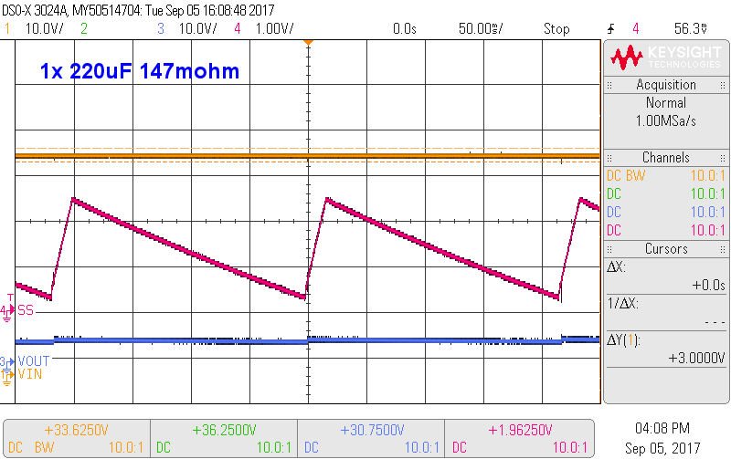
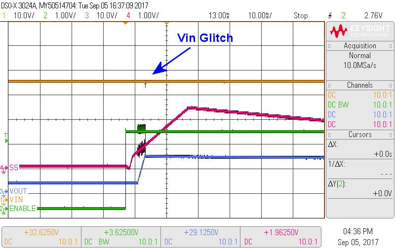
  • Thanks David.  Vin (shown above in yellow trace) is stable for >250ms before the regulator is enabled.  The problem persists with or with the 220uF input capacitor.

  • Hello,

    Is it possible for your to post the part number of the electrolytic or let me know what the specified ESR of the input capacitor is? Looking at your waveform's the SS is cycling whether the output voltage reaches the set point or not. I still think damping the input cap with a higher ESR is worth trying. For the calculated required ESR = Sqrt(Lfilter/Cin); where Cin is the Cin of the ceramics used. Make sure the Cin (electrolytic) is at least 5 x>Cin (ceramic).
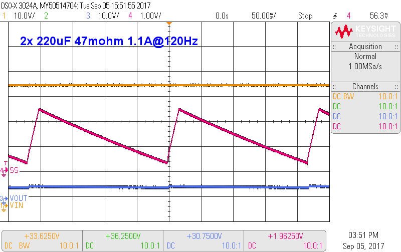
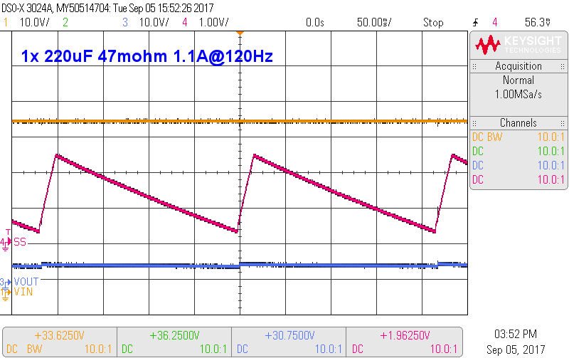
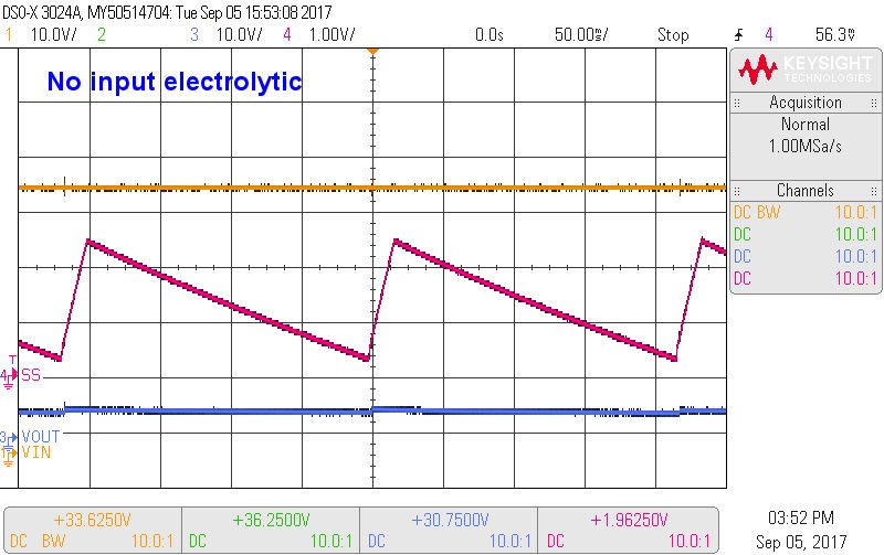
  • I have a Rubycon 100ZLJ220M12.5X25, 220uF 47mohm electrolytic on the input filtering.  There is 42uF of ceramics on the input, with an additional 20uF at the power supply input (prior to 2.2uH filter).

    I tested with 2x220uF, 1x220uF, no electrolytic and also a 220uF with a 100mOhm series resistor.  The regulator couldn't startup if the output was pre-biased, unless I waited until the output voltage reduced below at least 2V.  

  • May have the solution.  Changed Css to 200nF and experiencing success.  Previously increased only up to 100nF (Webench used 2.2nF).