This thread has been locked.

If you have a related question, please click the "Ask a related question" button in the top right corner. The newly created question will be automatically linked to this question.

TPS53647: Loop Response Question

Part Number: TPS53647

Hi,

I am looking at measuring the loop response for a 2-phase TPS53647 design.


In section 6.2 of SLUUBA9A, the TPS53647 EVM User Guide, it describes where and how to measure the loop response of the TPPS53647. 


It says to put the perturbation on J8 and then the output is measured between J7 and J8.  J7 is at Vout and J8 is at VSP/VSN.


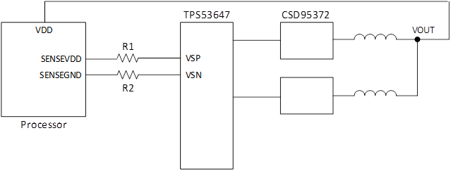
We have a processor in the feedback path as shown below.  I am just looking for verification that I am on the correct path.


  • Use an isolation transformer to inject the perturbation between VSP and VSN.
  • Measure the result across R1


Is this correct?


 Thanks,

David

  • Hi David,

    It sounds like you're on the right track save for one thing. The perturbation signal is injected across the 10Ω resistor, R64, not from VSP to VSN. In section 6.2.1 of the user guide the NA signal is placed from J8+ to J7+ which is across the resistor. It's a small difference but an important one. This way the perturbation isn't sent to GND at all and the loop can be properly measured.

    Your NA probes would then be placed according to the rest of section 6.2.1 from VSP to VSN.

    If you have any other questions please let me know.

    Thanks,

    Carmen
  • Hi Carmen,

    We are using dual phase for current design, so we will tie CSP3 & SCP4 to V3R3 as recommended.


    The phase question was the phase relations (interleaving) between the two phases when in dual phase mode and between the three phases in tri-phase mode.  According to the datasheet, the answer is 360/n.  So in dual phase mode, switching at 180° apart and in tri-phase is 120° apart.  You can confirm that for me.


    We typically like to know the loop compensation response for designs…  I had a TPS53647 Webench circuit, but it didn’t allow me to do loop compensation or bode plot.  Webench can only do 4-phase.  So for 60A dual phase design, we can use the loop compensation as quad phase 120A?


    For switching frequency at 600KHz, the datasheet calls out 39KOhm.  39K is not a standard value while 39.2K is a standard value.  Can we just use 39.2K standard value?  How sensitive is the device to the value?  

    Thanks,

    David