


Other Parts Discussed in Thread: PMP9563
I have been confused with the switching duty cycle control of TPS23754.
For different output load (12V, 0A ~2.5A), the Primary MOSFET almost does not change duty cycle.
A interesting phenomenon is that minus current in primary side.(DCM)
As output load increases, the negative current decrease to zero and then system works in CCM.
Attachment was measured voltage across R15 on PMP9563.(represents Primary side current)
(PMP9563 is Forward topology. For fly back application, I also measured the same result on other boards)
I am curious about
1. Why does the negative current appear at R15?
2. Why does TPS23754 NOT change switching duty cycle while output load changing.
12V/0A output: 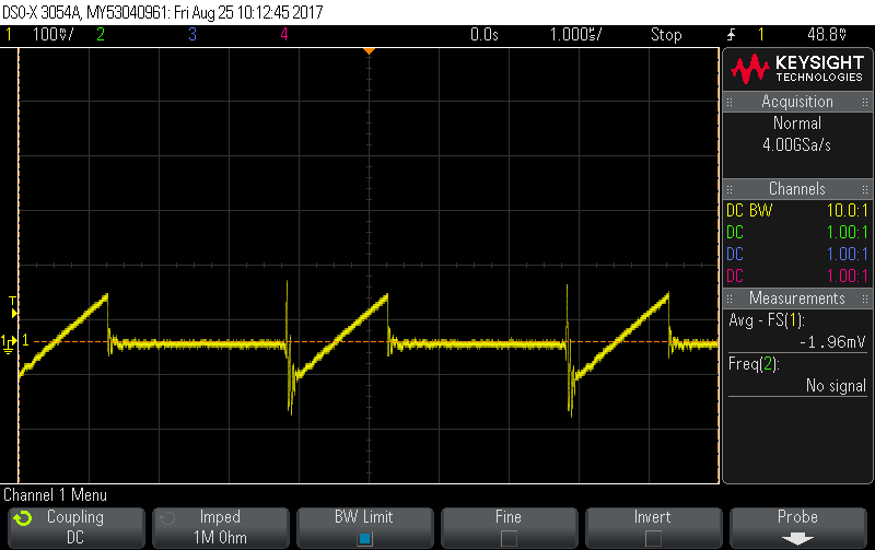
12V/0.5A output: 
12V/1A output:
12V/2.5A output: 

