This thread has been locked.

If you have a related question, please click the "Ask a related question" button in the top right corner. The newly created question will be automatically linked to this question.

TPS61089: system efficiency is low

Part Number: TPS61089
Other Parts Discussed in Thread: INA199, BQ25703

Dear sir,

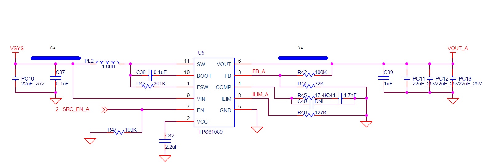
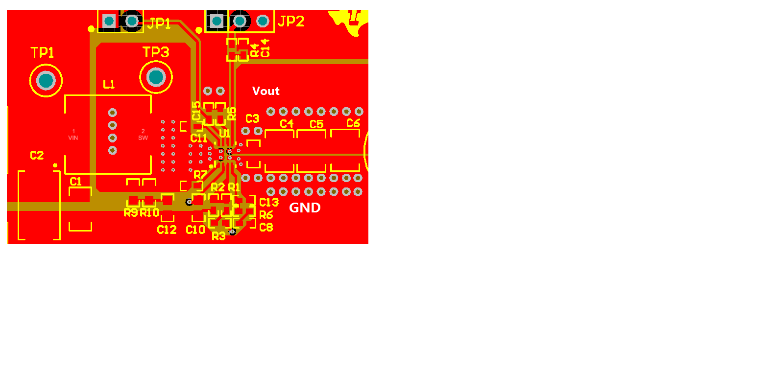
I used the TPS61089 for 1S battery boost to 5/9/12V. The function works. But the system efficiency is very low. When I input 4V, output 5V/1A, 9V/1A, the system efficiency is only 83%. How can I improve for it?

Thanks  

  • what is the part number of the inductor you are using?
  • Thanks Jasper.

    Hongren,

    For the TPS61089 , to get high efficiency, two things is of upmost important.

    1. The selection of the main inductor, please attached the datasheet of this inductor.

    2. The PCB layout, make sure the pcb is not  overheated. The power path has poured with enough copper.

  • Hi Helen and Jasper,

    The inductor I used is LVS808040L-2R2□-AU. inductance is 2.2uH, test freq is 100kHz,1V, DCR is 12mohm,  Isat is 7.2(6.30)A, Irms(A) is  7.3(6.40), tolerance is 20%.

    the layout is attached. It is a 4 layer board. The board is 2oz copper on top/bot and 1.5oz copper in L2/L3.

    I have ever suspect if the layout can support enough current. But I test the output current on 1A ,2A, 3A. The efficiency is similar. The efficiency is 83% @ 5V/3A. Mostt are about 77%.

    I measured the input voltage at Vin and output voltage at Vout.

    Thanks

    BR

    Ren


  • Thanks for the update.

    1. which place did you test the Vin and Vout. Because I found the output GND is connected by 6 very small via. The via will have big resistance.  I suggest you direct test the Vo at the IC's top side, just at the output cap.

    2. Which place did you test the Vin?

    2. I didn't found the core material of the indcutor you used, do you know what kind of core material is?

  • Hi Helen,

    I measured the Vin on the inductor.  It is VSYS on my board.

    I measured the Vout on the Vout capacitor. It is Vout_A on my board.

    The ground is PGND on my board. The PGND is a big plane on the GND layer. The output GND has 6 vias connect to layer 2. The vias is 12mil hole. In our practice, it is already big enough. Generally we use 8mil vias.

    I don't know because there is no information for the core material in the datasheet.

    Thanks

    BR

    Ren

  • Thanks. Your test place is OK!

    Can you conact with the inductor supplier for the core material information?

  • Hi Helen,

    I'm sorry that I got the wrong PN before.

    The right PN is ATNR8040M2R2MTand here is information. Pls check.

    thanks

    BR

    Ren

  • The inductor is also OK! It's strange!

    Did you test the thermal in this design?  Since there's few vias near the Vout pin and GND pin, the thermal will be A problem.  Please refer to the following layout:

  • Hi Helen,

    I test the thermal as follows:

    Ambient Temp:26.4
    Target Vin Iin Vout Iout efficiency T_induct T_61089
    5V/1A 3.94 1.51 4.96 1 83.37% 29 33
    5V/2A 3.86 3.07 4.95 2 83.54% 38 44
    5V/3A 3.76 4.85 4.94 3 81.27% 63 70
    9V/1A 3.87 2.83 8.93 1 81.54% 37 44
    9V/2A 3.66 6.4 9.13 2 77.95% 97 102
    12V/1A 3.8 3.98 12.04 1 79.61% 53 64
    12V/1.5A 3.67 6.41 12.09 1.5 77.09% 49 97

    When I test the 12V/1.5A, the chip temperature rise to 97 and ten restart.

    Pls check it.

    Thanks

    BR

    Ren

  • The thermal test result is really bad. With the TPS61089 EVM,

    1. the Temp when Vin=3.6V, Vo=9V/Io=2A is lower than 65C.

    2. the Temp when Vin=3.6V, Vo=12V/Io=1.5A is lower than 75C.

    I suggest you to relayout the PCB according to the TPS61089 EVM. 

  • Hi Helen,

    I don't think the low efficiency is caused by the layout directly. When the current is small, the efficiency is also low. 5V 1A, 5V 2A and 5V 3A have no big difference. And the themal for 5V 1A is OK. 

    The EVM has better thermal data because it has much space for the heat dissipation. But I need to put BQ25703 and TPS61089, BQ 2973, INA199 and other chips in a 60x30mm board with 4 layer..

    Now I have found some clues it may caused by other parts. I'm now trying to find it.

    Thanks

    BR

    Ren

  • What kind of clues do you found?

    The efficiency of the boost stage is only determined by the Boost IC and the inductor. Suggest you firstly change a even better inductor to check whether it can be help. The DCR of the inductor in the EVM board is lower than yours, but I think this only affect 1% efficiency. Then the other part comes from the Boost stage layout. the big trace loss.