Because of the Thanksgiving holiday in the U.S., TI E2E™ design support forum responses may be delayed from November 25 through December 2. Thank you for your patience.

This thread has been locked.

If you have a related question, please click the "Ask a related question" button in the top right corner. The newly created question will be automatically linked to this question.

TPS40170: 24VDC Switching Power Supply circuit failing on new batch of boards.

Part Number: TPS40170

We have been using a TPS40170 Switching Power Supply circuit for several years, 100's of boards, with no problems. We just started using the first (14) boards from our first batch of new 2017-manufacture boards and the TPS40170 power supply circuits are failing. We have regulated 48VDC (Off-the-shelf 1,000  watt Cosel Power Supply) providing the input power, the output voltage is 24VDC @ 5A, 300kHz switching frequency. We are only running with a 200mA load right now. The TPS40170 chips used in the failing circuits all have a 65K date code (May 2016?). We believe the passives are the correct values, but some of them cannot be accurately measured in circuit.

The failure mode is that when we first power up the boards, the 24VDC output fluctuates from 4 - 6VDC. We can disable the ENABLE line and then enable it and the circuit behaves the same. We have captured many waveforms of an operational board and a failing board and noticed some differences. All waveforms are triggered by the rising edge of the first HDRV signal. We have not been able to locate any TI documentation that goes into fine enough detail on the power-up operation of the TPS40170, so we are hoping to get an expert who can help us understand what exactly we are seeing.

We are not debugging a new design, but a new build of a design that has been working on 100's of boards before this first 2017-manufactured batch. We are hoping that the information below will mean something to a TI expert. It does not look like the circuit has excessive noise, as it will almost work if we use a bench supply and slowly increase the input voltage, but it is unstable. The old boards are rock solid in operation.

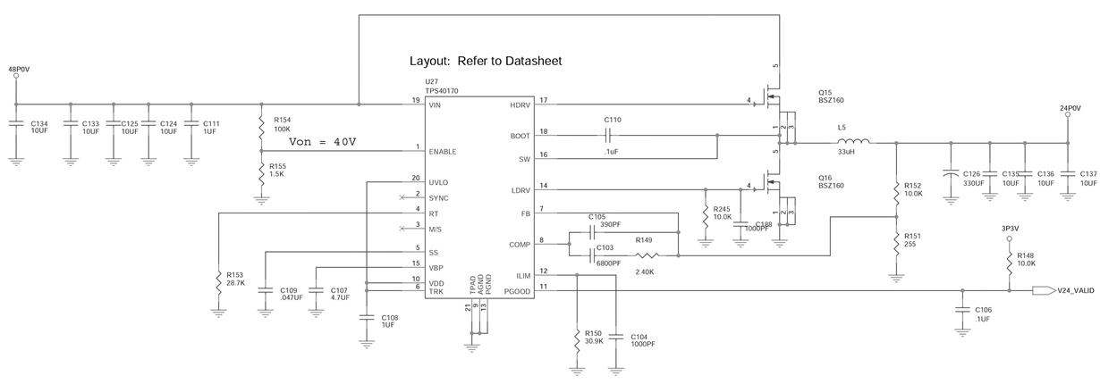
SCHEMATIC

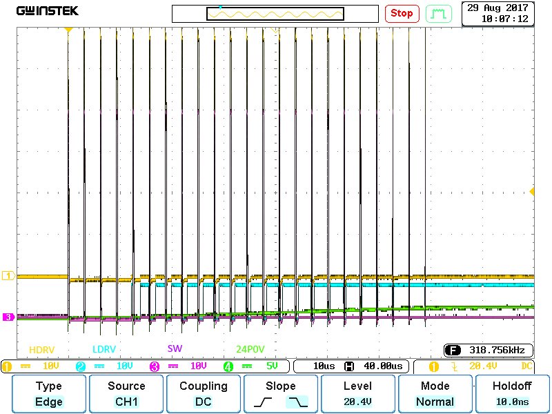
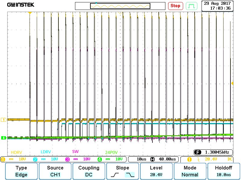
1) On the GOOD board, when the FET drivers (HDRV and LDRV signals) first start up, there is a burst of 23 HDRV pulses at 300kHz on the GOOD board. There are 28 or 29 pulses in the BAD board.

GOOD Board HDRV LDRV SW 24P0V Signals (10us/div)

BAD Board HDRV LDRV SW 24P0V Signals (10us/div)

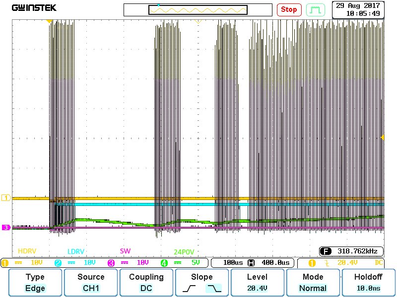
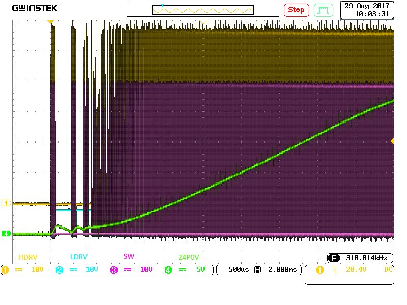
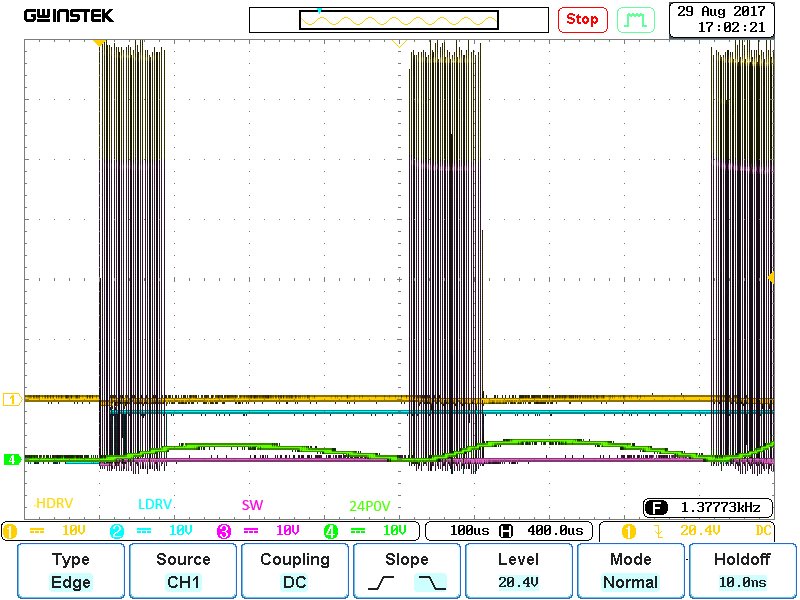
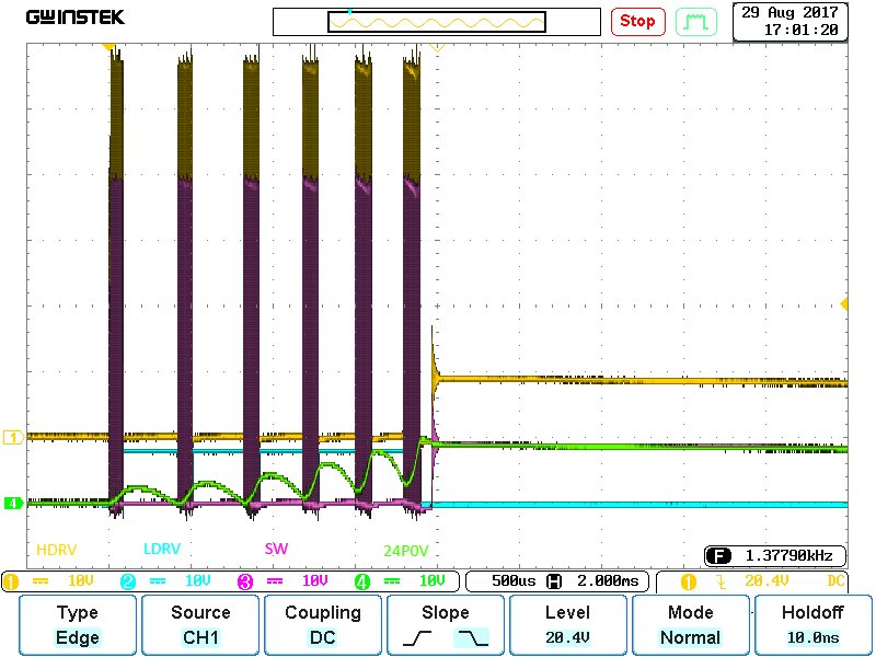
2) On the GOOD board, after the FET drivers (HDRV and LDRV signals) have started up, there is a spacing of approximately 200us between the first burst of pulses and 2nd burst, and then only approximately 100us between the 2nd and 3rd burst of pulses, then 50us between the 3rd and 4th bursts, then the pulses are continuous and the 24P0V signal rises up to 24V in about 4.5ms. On the BAD board, there is approximately 300us (a little less as the bursts continue) between bursts of pulses between the 1st and 2nd and 3rd and 4th bursts, then approximately 200us between the 4th and 5th and 6th bursts, then the bursts stop. Also, the 24V reaches almost 10V and then starts to drop.

GOOD Board HDRV LDRV SW 24P0V Signals (100us/div)

GOOD Board HDRV LDRV SW 24P0V Signals (500us/div)

BAD Board HDRV LDRV SW 24P0V Signals (100us/div)

BAD Board HDRV LDRV SW 24P0V Signals (500us/div)

Thanks for any help you folks can provide.

  • Hello Dave,

    if you take a device from the good batch and place it into a bad board, does the issue you are experiencing on the bad board go away?

    I suspect that the TPS40170 is going into current limit at start up. Taking a scope shot of SS will give us a clue that this is what is going on? Seeing as the TPS40170 senses the RDSon of the top FET, any instability due to the input impedance can cause a false current limit event. Have your cables and/ or has input power supply changed?

    I would first rule out that the old devices installed in the new board fixes the issue?

    hope this helps?

    David.
  • David,

    We are arranging to have parts  on a GOOD and BAD boards replaced by our board assembly house. We tried to remove a chip ourselves, but the VQFN package with it's thermal pad and lead-free solder proved to be too stubborn and the part and PCB traces were damaged, so time for the experts. We should have this done in the next day or so.

    We are using the same power supply and input power cable as always. The input power cable is 8 inches long and consists of two 16AWG positive lines and two 16AWG negative lines. The heavy wiring is because the board has other circuitry that control  48VDC, at up to 20A; the high power circuitry has its own power planes and is disabled during the testing of the TPS40170 24VDC circuitry.

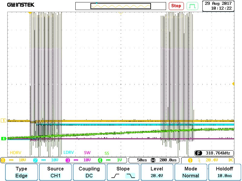
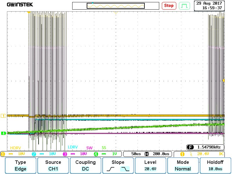
    Below are the GOOD and BAD SS signal waveforms. It looks like the SS signals are similar during the first 500us of operation. The biggest difference is still the spacing between the bursts of HDRV & LDRV signals and the number of pulses in each burst. There must be an explanation of why the TPS40170 decides to change those two parameters between a GOOD circuit and a BAD circuit? The SAS signal does eventually become different, but I need to take some new measurements with a longer timebase. I will get these done this morning.

    GOOD Board HDRV LDRV SW SS Signals (50us/div)

    BAD Board HDRV LDRV SW SS Signals (50us/div)

    Thanks,

    Dave M.

  • Hello Dave,

    Thanks for taking a scope capture of SS.

    Can you please let me know what your ESR of your output capacitor is.  I would like to check stability of your control loop.  Thanks.

    kind regards,

    David.

  • David,

    There are three 10uF ceramic capacitors, TDK C3216X5R1H106M, and one 330uF electrolytic capacitor, Panasonic EEE-1VA331P, in parallel. The ceramic capacitors each have an ESR of 2.2 milliohms @ 300kHz; the electrolytic capacitor ESR is not publishes by Panasonic and they have been difficult to talk to, so I submitted an email request for the information. I would estimate between 0.3 and 1 ohm.

    Regards,
    Dave M.
  • Hello Dave,

    I calculate from the tan delta that the ESR ~0.6ohm. If I am right, you are marginally stable. Please can you add an R(ff) and C(ff) across R152.

    Make:
    Rff = 500ohm
    Cff=2.2nF

    Hope this helps?

    Kind regards,

    David.
  • David,

    I do not think I can add a 500ohm resistor across R152, it will change the output voltage setting of the R152/R151 voltage divider. Maybe there is a different location I should use?


    Regards,
    Dave M.
  • Hello Dave,

    Sorry if you misunderstood. I am saying place a Resistor and Capacitor (in series) of the values mentioned, in paralell with R152. The DC output voltage will not change due to the Capacitor in series with the 500ohms. Hope this makes sense?

    David.
  • David,

    Misunderstood is an understatement. Of course you wanted them in series. The fix works. The circuit functions correctly at Vin from 25VDC to 48VDC. The waveforms closely resemble the GOOD waveforms. We tested Output Voltage vs. Current from 1A to 4.5A, results were almost exactly the same as the GOOD board.

    I am curious, when you calculated ESR, what tan delta and frequency did you use? ESR=tan delta * (1/(2*Pi*F*C))
    We thought the ESR of the 3 ceramic capacitors would override the ESR of the electrolytic capacitor? Without changing the PCB artwork or adding additional components, is there any changes we can make to the 4 capacitors so we would not need the extra RC?

    Do you believe this rework is a reliable, final fix? What would be the root cause of the failure? What exactly is this RC doing that makes up for the ESR-caused instability?

    We have just over (200) boards in the field for the last 3 years and have never seen this failure mode. We have (100) boards assembled in June & August 2017 and they all fail. All of the parts are the same, or at least should be (except new lot of PCBs). We can assume that the date and lot codes for all of the parts are different for the 2017 batch then the others, as the 2017 batch was built at least 7 months after the last 2016 batch. We also removed the electrolytic capacitor on a BAD board and replaced it with one a couple years old and the board still failed. Just FYI, this circuit was designed back in 2013 by a design house, so I do not know why they chose the component values and circuit design that was used.

    We should have the test boards, where the old IC is put on a new board and a new IC is put on an old board, either tomorrow or Tuesday and we will post the results.

    Thank you for your helpful suggestions and for working with us on this issue.


    Regards,
    Dave M.
  • Hello Dave,

    That’s good and bad news, sorry to hear the bad!

    You are correct; the Tan delta is spec'd in the Datasheet at 120Hz so when you evaluate the formulae you get the 600mR.

    The 3 ceramics do affect the output impedance and being low ESR, this is not good for a Voltage mode controller. The ESR on the output capacitor actually helps compensate the loop to yield sufficient phase margin.

    You can remove the 3 ceramics, this will give you a larger ripple voltage on the output, but I am not sure if this is an issue for you?

    The fix I gave you is a reliable fix, as it provides enough phase margin to ensure stability taking into account variations you will see in the output impedance.

    The issue is not with the IC, but it’s with the output capacitors. I suspect if you swap the output capacitors from the good board to the bad, your issue will be resolved also. But I can tell you from the datasheet specification, I think you were fortunate to have a stable design in the first place?


    Hope this helps?

    Kind regards,

    David.
  • David,

    We have the results from the swapped boards. Both of the GOOD boards continued to work and both of the BAD boards continued to fail. On one pair of GOOD&BAD boards we swapped the TPS40170, and on the other pair of GOOD&BAD boards we swapped the two transistors. Since the behavior of the modified boards did not change, it does appear that the BAD boards are failing due to a PCB error or due to the remaining discrete parts (such as the output capacitors). At least we know the addition of the compensation RC across the top feedback resistor will get rid of our problem.


    Regards,
    Dave M.