This thread has been locked.

If you have a related question, please click the "Ask a related question" button in the top right corner. The newly created question will be automatically linked to this question.

CSD95379Q3M: Startup problems when used in an H bridge for TEC control

Part Number: CSD95379Q3M
Other Parts Discussed in Thread: LP2985,

I'm having some issues with this part not switching on startup.   I'm using two of these to form an H bridge for bipolar control of a TEC element.
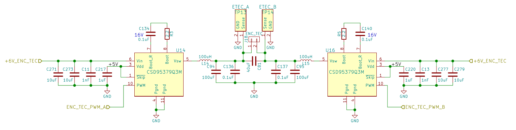
My setup:

Vdd = 5V, Vin = 3V

Skip# tied to Vdd

Bootstrap capacitor is 0.1uF with a 2.2 ohm resistor to slow down the switching times

I'm using a microcontroller (Cypress PSOC 5LP family) to drive the PWM pin.

The symptom is that when I first apply power, the Vsw node goes high and does not change no matter what pulses I apply to the PWM pin.  The only way I can get it to start switching the Vsw node is by briefly interrupting the power to the board - if the interruption is short enough (maybe 0.1-0.2 s) then it will start switching and operate normally.

The Vdd supply comes up very quickly.  The microcontroller takes a little more time to initialize.  I can see the PWM pin float at first before the microcontroller comes on line.  After that, it doesn't seem to matter what I do to the PWM pin - high or low level, high or low frequency.

Any help would be most appreciated - I'm working on a prototype and I don't think a user instruction to "jiggle the power cord" to get it to run will be well received.

Thanks!

  • Hello Thomas,
    I sent this one over to our applications team so hopefully I will have a response for you shortly.
  • Thomas,
    Applications asked if you could provide a schematic and waveforms for PWM, VIN, and VSW to help them in assisting you with this inquiry.
  • Attached is the schematic, I should be able to capture the waveforms later today.  

    +6V_ENC_TEC is the 6V supply for the TEC.  There is another copy of this that is fed with 3V and has two filtering stages (i.e. L14 and C94 are followed by another LC stage).

    Vdd is fed with +5V from a LP2985 linear regulator, not shown.

    The ENC_TEC_PWM_A and B signals are direct from the microcontroller.  The microcontroller operates at 3.3V.

  • Thanks Thomas,
    Let me know when you have the waveforms and I will forward all this material to our applications experts.
  • I've attached three captures of the same signal at different time scales.  One overview and then details of the first few milliseconds and also detail of the PWM starting.  Let me know if you need anything else.

    Thanks for your help!

  • Thomas,
    See our teams response below:

    "I’ll suggest to first check Power Stage soldering, one simple way is to disconnect the two output inductors and test each Power Stage independently: apply VIN, VDD and external PWM to see if each Power Stage can work normally (PWM high will pull VSW to VIN, PWM low will pull VSW to GND). Please check the two PGND pins of Power Stage (Pin4 and pin11) and make sure they are connected on PCB.

    If the Power Stages can work as expected, customer need to check the system design such as the timing for the two PWM signals, etc... "
  • Thanks for the response.  

    I've got two boards for testing, and on each board are two H-bridges for a total of 8 of the CSD95379Q3M parts.  I have visually inspected and tested as above and they all behave similarily, so while I wish it was a simple soldering problem I have serious doubts that they all have the exact same problem.

    Also, they will work fine if I interrupt the power very briefly.  See the attached scope capture - the setup is identical to the previous captures except that I removed a startup delay in the microcontroller.  I applied power and saw the same signals as above, then I interrupted power briefly and the part works beautifully.  In the attached capture, you can see that at first the part isn't responding to the PWM signal, then power is interrupted and you can see the PWM signal stop as the microcontroller loses power and Vin starts to droop.  When power is restored you can see Vin come back to 3V and when the microcontroller finishes startup the part now switches fine.  This behavior has been repeatable across all copies of this circuit.

    Can you be more specific about what you mean by "timing for the two PWM signals, etc."?  Since I'm applying identical PWM signals and the part either works or not depending on startup conditions it seems like it isn't on the PWM signal side.  Is this part sensitive to power sequencing between Vdd and Vin?  Should I have control over the Skip pin?  I'm going to have to make a decision in a few days as to how to fix this and my testing time ends Friday.

    Is there someone I can call to discuss this in real time?

  • Thomas,
    Sorry I was in a meeting when I missed your call.

    We are used to working these more technical trouble shooting issues through a sales contact or field apps but that may or may not be an option for you so I alerted or apps team that you are in a hurry to have this issue resolved.

    They asked if you could do the following:

    1: Please capture VIN, #SKIP, PWM and VSW for one Power Stage on the same picture for the following two cases:

    (1) First start up (no Vsw response)
    (2) Startup after Power Interruption (normal Power Stage operation)

    Please check the rise time of SKIP#. Before Power Stage came back to normal, which power was interrupted (VIN, 5V)?

    2: please also measure the BOOT-BOOTR waveform
    3: please measure pin4 PGND waveform to make sure PGND is stable.
  • See below for the requested waveforms.

    I don't have the ability to switch Vin or Vdd individually, I am only switching the main power input to the board that feeds the various step-down regulators.  Their individual behaviors will be determined by their filter capacitance and their loads.

    SKIP# is tied to Vdd by a trace that connects pin 1 and 3.  For the waveforms below, I attached a wire to the junction of pins 1 and 3.

    When collecting these waveforms, I noticed that it was less likely than before that the part would start correctly when I cycled power.  I did solder short wires to the various pads so that I could probe them reliably, but it seems unlikely that would have an effect here.

  • In a little further testing, I found that having the load connected made it much more likely to start up after interrupting the power. The plots in the previous post were taken with the load disconnected.
  • From our apps engineer:

    "I saw a very long PWM high at the beginning of power-on, could you please check why such long PWM high is needed?

    In the driver IC, the bootstrap circuit will charge the boost cap when Low side is on; with such a long PWM high, the BOOT voltage will drop and may cause the malfunction of the gate driver IC. Could you ask the customer to change the PWM pattern to test the circuit? I’ll suggest to have PWM low first and then PWM high at power-on and don’t use very long high PWM pulses."
  • Thomas,
    Our apps team noted that if PWM is floating, it should stay in the tri-sate with 5VDD since there are pull-up and upll down resistors at the Power Stage PWM pin in the driver IC. So something external must be pulling PWM high in the circuit.
  • I have the same problem when i using this module in a half bridge inverter. When i using a metal bar to touch the bootstrap capacitor then it startup. I don't know why it is. And i am looking for the solution. If there are any solutions please tell me. thank you.
  • Since I have not heard back from Thomas on this, the best way to get your question answered would be to start a new thread, provide some waveforms and schematic, describe the problem you are experiencing in detail, and we can proceed from there.
  • Sorry for the long hiatus in responses - I was out of town for a while and I wanted to make sure my fixes worked before posting about it.

    I added a 10k pull-down resistor to the pwm line, which seems to be enough to overcome whatever internal leakage there was during the microcontroller startup but doesn't hurt the normal operation.  With this pull-down in place I haven't had any more startup issues.

    Thanks for all your help!

    -Thomas