This thread has been locked.

If you have a related question, please click the "Ask a related question" button in the top right corner. The newly created question will be automatically linked to this question.

BQ25601: Transient response to load steps

Part Number: BQ25601
Other Parts Discussed in Thread: TPS54240

After a lot of tests and efforts with BQ25601 I have concluded that the chip is not able to respond instantly to load steps when it is in suspend mode.

Below I describe two cases, when battery is present and not.

Battery not present.
If battery is not present and charger is enabled (CE\ Low), it is not capable to provide current to heavy loads without significant droop on VSYS rail.
In the same case, if charger is disabled, it's responded perfectly to step loads. The voltage droop on VSYS is negligible.

Battery present
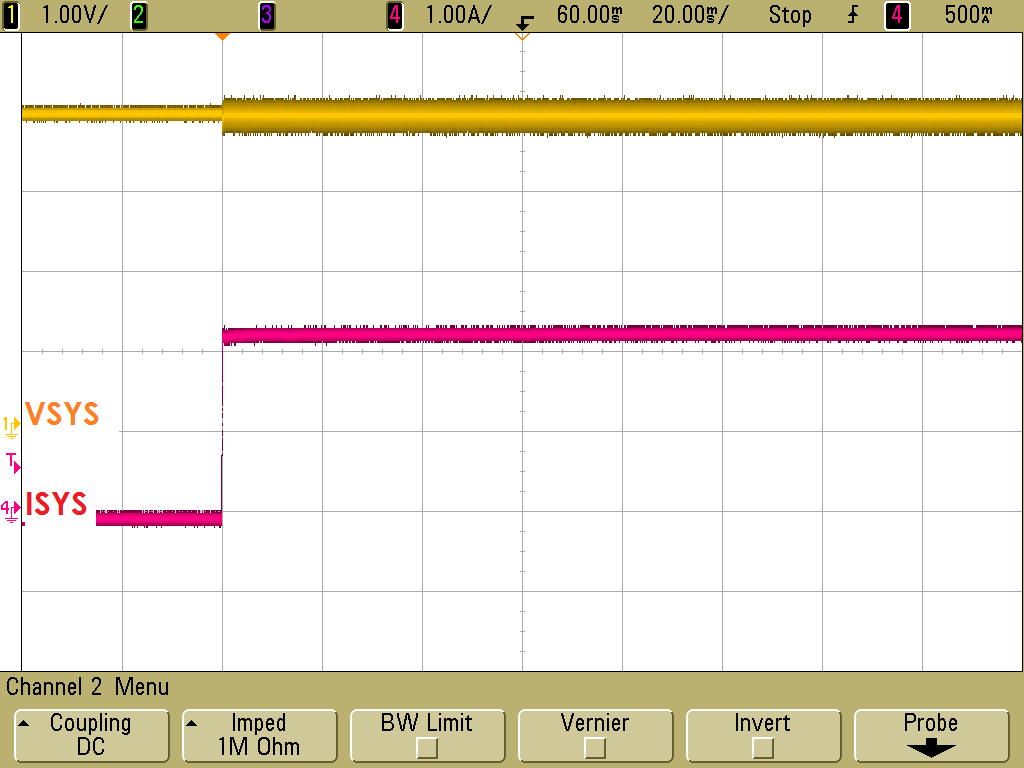
In the contrast, If the battery is connected irrespective of its voltage level (even with fully discharged battery Vbat < 2.7V) and CE\ status, there's not droop on VSYS rail for the same loads, at all.
In this case, CE\ does not matter. Either LOW or HIGH, transient response to load steps is perfect.

Test conditions and settings.

With host:
VIN = 5V, 2.5A (TPS54240)
IIDPM = 3A
VINDPM = 4.5V (default)
ICHG = 300mA
PRECH = 60mA
ITERM = 60mA
VSYS_min = 3.7V
Csys = 2x10uF + 3x47uF
RL = 2 Ohm
Watchdog disabled

Without host, standalone:
VIN = 5V, 2.5A (TPS54240)
PSEL = LOW (2.4A)
Csys = 2x10uF + 3x47uF
RL = 2 Ohm

Any advice would be appreciated.
Did I do something wrong here?

I upload a diagram of my setup


  • Hey GeT,

    When you perform the test with the battery attached + the input DC/DC source, is there current supplied by the battery? 

    If not, is the battery receiving the full charge current?

    Regards,

    Joel H

  • As I described in second case, the level of battery doesn't matter. It can be fully discharged and either it is charging (CE low) or not (CE high), VSYS rail is quite stable.

    If input's current is limited (eg IIDPM=1A) and battery has sufficient energy level, then yes, it will supply some current as datasheet mentions in supplement mode.

    But in my case supplement mode doesn't engage because IIDPM is set to 3A and my load causes 4.2V/2R maximum. I draw less current than my limitation, even less than my input source.

    While charging phase, my battery can receive as much current as I set in ICHG register, which I selected to be 300mA.

  • Hey GeT,

    I am actually more concerned with VINDPM. This can be tripped if the input voltage falls too low, typically from long leads to the charger and somewhat heavy input current. If there is enough voltage droop from your source (TPS54240) to VBUS of the charger, you could inadvertently fall into VINDPM.


    Regards,
    Joel H
  • I checked this as well there's no voltage droop on the output of TPS54240, I measured as close as possible to vbus. Also, notice that there's cases in which VSYS doesn't drop at all. Those cases are: battery on and CE high or low, battery off but only with CE high.

    The problem is when chip enters in suspend mode (CE low - battery off)

  • I checked it again, no voltage droop, when switch closes, at all. I measured as close as possible to VBUS, voltage is quite steady at 5V
  • Hey GeT,

    I will get investigate this in our lab today to see if I can replicate what you're seeing.

    Regards,

    Joel H

  • Thank you Joel, I'm looking forward for your reply.

  • Hey GeT,

    Unfortunately, I was not able to see the same thing on our EVM.

    Please see the following waveform with a 1Ohm load switched in.

    No battery was attached, /CE was HIGH (disabled charge), and even added much more output capacitance for different trials, even up to 470uF extra to see if it affected the loop response. Again, however, I could not replicate the VSYS drop you are seeing.

    Is there anything else on the EVM you may have changed or anything about your test setup that may be limiting current or triggering one of our DPM loops?

    If you can, add an external power supply to the middle pin of JP4 (to retain communication), and when you switch the 2Ohm load, please read out and send the register values here.

    Regards,

    Joel H

  • Thank you very much for your time you spend to help me with this.

    You didn't see what I'm seeing because as you mentioned you had CE\ pin high. Pull it low, and just connect a heavy load on Vsys rail (do NOT use battery). Open and close the switch many times while watching oscilloscope.

    I have mentioned that, when the CE\ is high the chip can respond perfectly. Pull it low when no battery is present and watch again.

    Thanks again.

    Regards

  • Hey GeT,

    I was able to replicate what you are seeing.

    When there is no battery present, but Charge is Enabled (/CE = LOW), there are several loops active simultaneously in the charger attempting the charge any capacitance on VBAT (this is the reason for oscillation of VSYS and VBAT). 

    When you apply this heavy load while a battery is not present, the system immediately falls very low as the VSYSMIN loop is not dominating the converter feedback. Because of this, VSYS drops below 2.2V, we basically enter Converter Start-up again (described in the datasheet under Section 8.4.3.5.). This limits the input current limit back to 200mA until VSYS can ramp up above 2.2V. However, because of the heavy load on SYS (2Ohm), it does not rise above 2.2V.

    My question is what operation do you have where the battery will not be present?

    Regards,

    Joel H

  • I intend to power GSM/GPRS module which demands peak current up to 2A while packets are transmitting.

    Can you give me a solution for this?

    The only solution I found is to disable the charger. However I don't know when the battery is going to be plugged in, on the board.
    MCU might catch the connection via Analog to Digital Converter, but it might be some circumstances which battery would be fully discharged (0V due to internal protection). 

    In addition, if battery switched off from the board, MCU has to disable the charger instantly.
    If this is not done instantly GSM might restart due to insufficient current on its power rail.

    Notice that there are some cases in which voltage does not drop below 2.2V because it rises again after the deep falling during load is on.
    If you try to set the switch on and off few times you might see this too.

    Which takes the control of VSYS feedback?

    I'm looking forward for your answers.

    Thank you again, Joel

  • Hey GeT,

    So the solution we found for your application is based on whether you have a thermistor attached to the battery at all? You may even consider using just a 10k resistor attached to the battery to signal an unplug event.

    Essentially what you would do it tie the thermistor connection pin to the charger's TS pin. This pin is used for a thermistor on the battery to disabled charging when the battery becomes too hot or too cold. If the battery is removed, the charger will automatically disabled charging as the TS pin voltage will rise above a certain threshold.

    Once you hit this threshold, you may use the fault indication on the charger (TS Fault) to turn off Q4. The fault will clear when you re-insert the battery (TS Normal). At this point, you may re-enable Q4.

    This solution should work for your application assuming you will use a battery attached thermisitor (which is actually quite common).


    Regards,
    Joel H
  • Unfortunately my battery does not have internal thermistor. I just followed the instructions without thermistor for my design. I placed two parallel resistors and one in series to REGN. Like evaluation kit does.

  • It's quite clever though, I will look into the possibility to get a battery with thermistor but at this time I will stick with my previous solution. I will going to detect the battery through ADC.
  • That also works.

    One question is if the peak load could be occurring at the same moment the battery is disconnected? 

    If not, then you can also use successive INT pulses from the charger to determine whether the battery is present or not. 

    Regards,

    Joel H

  • That's an interesting question!

    The load steps always depend on GSM/GPRS packets.

    Even though it provides an PIO (RFSYNC) signal which could notify the mcu when it is going to transmit a packet, I'm worried about the repetitive ON/OFF of the charger.

    The charger has a timer on it, and it resets every time CE\ goes from HIGH to LOW.

    Also this useful PIO signal might be output for various events not only transmission notice

    How can INT pulses can inform my mcu whether the battery is present or not?
    Do you mean that I could catch (throught I2C) the "suspend mode" when the charger enters in this mode?

  • Hey GeT,

    INT will continue to trigger when charge is enabled and there is no battery. When there is no battery, and the load is not significant, then that signal will consistently show a "Charge Complete" INT pulse at a fixed interval.

    That is why I asked whether your pulsed GSM/GPRS packets happen at any point or whether there is a known time when the battery will be removed.

    You also mentioned the charger has a timer on it that is reset every time /CE transitions. Are you referring to the safety timer?

    And again, refer to my previous statements regarding your last question. If the battery cannot be removed during a peak load, then you may use the INT pulse to show that you are entering and terminating charge over and over again (this is the waveform you see without a battery and /CE low).


    Regards,
    Joel H
  • I don't know when the battery is going to be removed from the board. It depends on the user. As I don't also know if the step occur at the same time that the battery will be removed.

    Regarding timer, yes I was referred to safety timer.
  • Hey GeT,

    Okay, I understand. Then my previous suggestion using INT will not be useful to you.

    My the only other option I could think of is a physical modification to the detachable battery pack you have. If it is possible. I would suggest again, using the TS pin with a 10k on the battery.

    Regards,

    Joel H