This thread has been locked.

If you have a related question, please click the "Ask a related question" button in the top right corner. The newly created question will be automatically linked to this question.

TLV62569: TLV62569 Chang work mode between Power Save Mode and PWM mode

Part Number: TLV62569

Dear all:

          I use two TLV62569 in my IPC products, one is from 3.3V to 1.5V for DDR ,other is from 3.3V to 0.9V for CPU Core. When I use this IPC,there are some ripple on the display screen . I test  their SW pin, the wave as blow:

(a)3.3V to 1.5V for DDR SW pin wave:

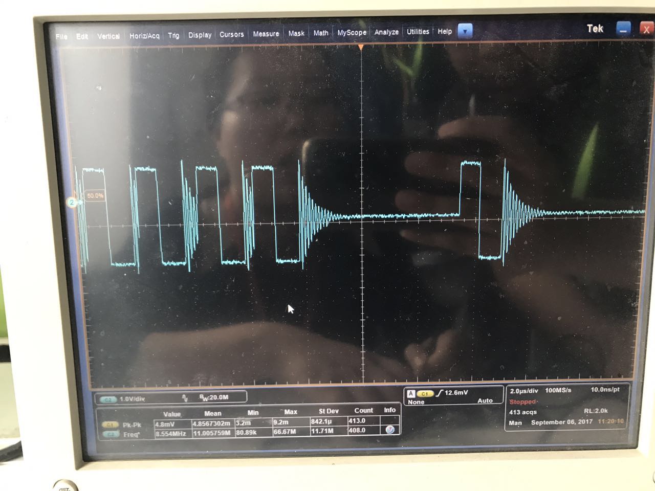
(b) 3.3V to 0.9V for CPU core SW pin wave:

I do not  konw why in the third picture, tlv62659 seem as work form  PWM mode to  Power Save Mode ,then turn back to PWM mode.Please tell me the reason , Is the ripple on the display screen  related to this reason?  Thanks a lot !

  • Hello Chen!

    It's a pleasure to support you. The waveforms you see depict a normal operation of the device, which has been designed in order to optimise the efficiency in the transition between PFM and PWM. That's why some cycles are in PFM and some in PWM.

    In PFM working operation, the switching frequency is decreased to enhance efficiency. But a higher inductor peak current is necessary in order to maintain the DC regulation . The higher ripple is hence a direct consequence of that.

    I hope I answered your question.

    Best regards,
    Emmanuel