This thread has been locked.

If you have a related question, please click the "Ask a related question" button in the top right corner. The newly created question will be automatically linked to this question.

TPS62160: Problem achieving -5V

Part Number: TPS62160
Other Parts Discussed in Thread: TPS60403, TPS562200

Hi !

we are using step-down converter TPS62160.

We have designed a PCB with 2 of this converters one for achieving +5V and other for -5V.

Input voltage is +12V.
We used components like described in datasheet.

+5V works great, but problem is -5V (schematics on p.25 of datasheet).


For Schottky diode we use 1N5819HW.

With combination of suggested resistors 680k and 130k, output voltage is around -3,7V and is unstable (swings from -3.5V to -3,9V).

We were experimenting with changing combination of resistors in FB.

We ahve achieved -5,10V with 300k and 43k with 44uF as output capacitor but also unstable nad after some time falls down to -3,7V.

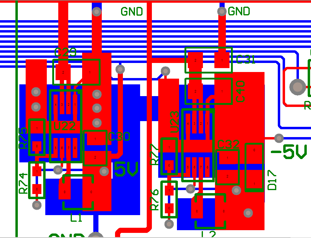
Here is a screenshot of PCB.

 On left is TPS62160(U22) which output voltage is +5V and works fine.

 On right is TPS62160(U23) which output voltage should be -5V.(PROBLEM)


Thank you !

  • From your layout image, it looks like you have a +12V to -5V converter? This is right at the voltage limit of the TPS62160. Better would be a +5V to -5V circuit.

    As well, many of the power traces (Vin and Vout) look very thin. They can not likely carry much current. How much output current do you need?

    It looks like C31 is the cap from Vin to GND (0V)? I do not see how its GND gets back to the GND at L2/C32. This loop must be small. You might try putting C31 on top of U23 and using wires to connect to Vin and GND.

    As well, you might try 68k and 13k resistors as explained here: www.ti.com/.../slyt469.pdf
  • Hi !

    [Re:]From your layout image, it looks like you have a +12V to -5V converter? This is right at the voltage limit of the TPS62160. Better would be a +5V to -5V circuit.

    OK, we'll try that

    [Re:]As well, many of the power traces (Vin and Vout) look very thin. They can not likely carry much current. How much output current do you need?

    @ +5V we need up to 100mA

    @ -5V we need to 50mA


    [Re:]It looks like C31 is the cap from Vin to GND (0V)? I do not see how its GND gets back to the GND at L2/C32. This loop must be small. You might try putting C31 on top of U23 and using wires to connect to Vin and GND.

    Bottom layer(blue) is GND, we try that too.

    We achieved -5V by TPS60403 which is very simple. All we need is 3 caps and chip.

    Yesterday we soldered same PCB and had a problem with +5V with TPS62160, same board, same components, doesn't work :-(

    We are aware that our PCB design is poor


  • Were you able to get this working?
  • unfortunately not :-(

    Now we will try with TPS562200.

    We have never ending problems with DC/DC converters. We have tried more then 10 of them.


    Documentation is confusing.

    For TPS562200 datasheet gives Layout Guidelines which is very different from one described in TPS562200 evaluation module.

    Which one to choose?


  • Wow. 10 DC/DCs is very unnecessary. We can get the TPS62160 working.

    Did you try moving C31 as I explained? Or the smaller FB resistors?

    Can you take a photograph of the PCB?

    Can you post waveforms of Vin, Vout, and SW when it is not working right?