This thread has been locked.

If you have a related question, please click the "Ask a related question" button in the top right corner. The newly created question will be automatically linked to this question.

LP8860-Q1: boost control topolgy

Part Number: LP8860-Q1

Hi team,

I have some question about LP8860-Q1:

  • I saw some discussion about Rsense selection, just want to clarify: for Rsense=25mohm, BOOST_IMAX_SEL=000 mean maximum current limit is 2A; for Rsense=10mohm, does BOOST_IMAX_SEL=000 mean maximum current limit is 5A?
  • Could you explain why we need sense the low-side switch current? For boost over-current protection? However, from the DS P43, over-current protection is achieved by detecting the Vboost.
  • For Fig.21, how to keep the output current constant since we didn't detect the LED current? 
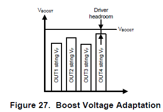
  • Since the output voltage is the same for 4 led strings,  the dropout voltage of LED strings may not be different even with a same current flow through. How to close this gap?

Thanks.

Dongbao

  • Hello Dongbao,

    Thank you for your interest in LP8860 device. I'll look into your questions and reply shortly.
  • Hi Dongbao,

    1.  Your calculations are correct, but  RSENSE resistor value will also affect internal boost compensation parameters, therefore there are limits to RSENSE resistors used. We encourage using 25mOhm resistor  per design recommendation.

    2.  Actual OCP condition is detected through RSENSE resistor,  but fault flag is set when, as datasheet description, Vboost stays 5V below set value longer than 110ms. When OCP  is detected, switching will stop if condition persists and as a result Vboost will drop, once it drops 5V below target value, device will wait 110ms and then set fault flag high. This will avoid false detection of OCP condition.

    3.  Boost converter only sets Vout voltage, but LED output current is set by LED driver block. Internal DAC will set ref voltage across resistor which will set constant current for LED strings.

    4.  Please refer to section 7.3.9.1. for detailed explanation. Boost adaptive voltage will adjust the Vout voltage to the string with the highest Vf, and as a result, the voltage at the LED output pins (OUT1-4), also called headroom voltage will be slightly different from one string to the other, compensating for this difference due to LED variation.