This thread has been locked.

If you have a related question, please click the "Ask a related question" button in the top right corner. The newly created question will be automatically linked to this question.

UCC28740: Diode with snubber circuit

Part Number: UCC28740
Other Parts Discussed in Thread: UCC28730, UCC24650

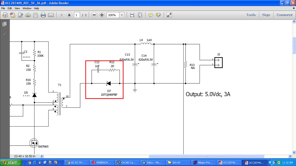
As per the reference design , Diode with snubber circuit on Negative path ,
As per the others design,Diode with snubber circuit on positive path

Which is correct,Please can u explain me in detail 

  • Baskaran,

    Both are equivalent - in both cases, the diode will rectify the current, and prevent it from reversing at the end of the Flyback interval.

    Putting the diode in the upper leg is more commonly used.

    In the lower leg, EMI can be higher.

    The lower leg is usually only used when necessary, e.g. when the secondary side PSR wake-up monitor us used (UCC24650 on the secondary in conjunction with UCC28730 on the primary), or if the diode is to be replaced with a synchronous rectifier FET (SR) - putting the SR in the lower leg is much easier to drive the GND-referenced FET and easier to bias the SR driver.


    Thanks,
    Bernard