This thread has been locked.

If you have a related question, please click the "Ask a related question" button in the top right corner. The newly created question will be automatically linked to this question.

UCC28710: Using UCC28710 in PMP40025 reference design

Part Number: UCC28710
Other Parts Discussed in Thread: UCC28730, , PMP40025

Dear All,

one of my customer working on PMP40025 reference design and we suggested to use UCC28710 instead of UCC28730 device for cost optimisation.

Following are the few doubts and clarifications I have: (In aim to reduce the cost of the converter)
1) In the same design replacing UCC28730 with UCC28710 produces different output at open circuit.
Ex: At a load of 120 mA, UCC28710 produces about 64.8 V, with UCC28730 it is limited between 48V to 50V. Please suggest reasons for this.
2) Whether UCC28710 can be used for 35W to 40W, with 48V o/p. , because I observe in webench design tool, the maximum voltage is about 25V as attached.

PMP40025 schematics.pdf
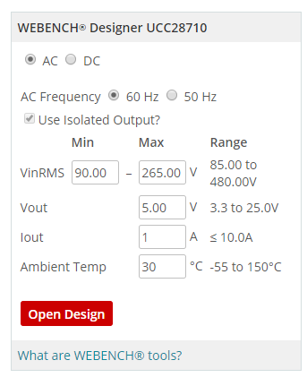
3) I observe that both UCC28730 and UCC28710 operates in the range of 25 kHz to 35kHz, Can it be operated in near 100kHz( UCC28710), whether this will help in reducing the size of secondary side capacitive filter.
4) Currently we use 47uF + 47uF after input side rectifier, any suggestions to reduce the value.
5) I would also like to simulate the converter and view the peak currents of primary and secondary in webench, but it shows the o/p voltage limit to 25V, as mentioned in 3)
6) Please suggest whether the components D8, Q3, R17 & D4 can be removed without affecting the safety.

TI design also attached for reference.

Rgds,

Aravind.

  • Hello Aravind,

    1 The UCC28730 and UCC28710 use a frequency (FM) and peak current mode modulation to control the duty cycle.

        a. UCC28710 fmin = 680 Hz

        b. UCC28730 fmin = 32 Hz

        c. The converters minimum duty cycle is based on the minimum frequency

        d. The UCC28730's minimum duty cycle for the same transformer can control down to duty that is roughly 1/22th of that of the UCC28710 minimum duty cycle.

    i. In the PMP40025 design changing the controller from a UCC28730 to UCC28710 would require a smaller pre-load resistor to keep the power stage in      regulation at no load to lighter load conditions.

    ii. If you drop R3 from 510K down to 23K ohms it should improve your light load to no load regulation.

    2. The UCC28710 should be able to be used in a 48V application similar to the UCC28730 in the PMP40025 design.

    a. The UCC28710 and the UCC28730 use similar control law and should be able to be designed for the same power levels.

    b. The WEBENCH design tool looks like it was designed to be optimized for a USB-PD output voltage range.

    c. There is a UCC28710 excel design tool that you can use to double check your deisgn.  You can find this tool at the following link and it is not limited to 25V. http://www.ti.com/lit/zip/sluc590.


    3. The primary magnetizing inductance sets the maximum switching frequency. Please refer to equation 16 in the UCC28710 data sheet for limiation.

    a. The UCC28710 and UCC28730 based on this limitation should run close to the same maximum switching frequency.

    4. The input bulk capacitors C2 and C3 of the PMP400025 should have been based on low frequency input ripple voltage.

    a. Theses designs generally target a minimum input bulk of around 70 V.

    b. If you decrease the amount of these capacitors you will have to redesign your transformer due to.

    i. The turns ratio ratio would have to change

    ii. Wires will have to be resized for higher RMS current

    c. I would recommend sticking with the current filter capacitors.


    5. Components D8, Q3, R17 and D4 form a series pass regulator to power the UCC28730/10 device.

    a. Resistor divider R5, R9//R10 is setup to control the aux at the knee to 16V.

    b. The auxiliary spike on the aux winding will be greater than 16V and by how much I don’t know

    c. The UCC2870 can handle a maximum VDD voltage of 38V, so I think you will be fine as far as the UCC28710 not being over voltage during operation.

             d. I don’t believe this circuit was added for safety.

             e. This circuit was added to improve efficiency and regulate the VDD voltage at a voltage lower than the aux winding voltage.

    Regards,


    Mike