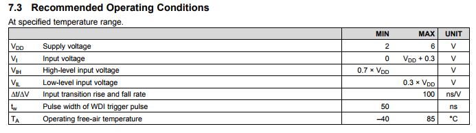
This thread has been locked.

If you have a related question, please click the "Ask a related question" button in the top right corner. The newly created question will be automatically linked to this question.

TPS3813: TPS3813K33, there is a signal at VDD, when WDD be removed and WDI input the signal, then the similar signal will be generated at some PIN.

Part Number: TPS3813

Dear expert,

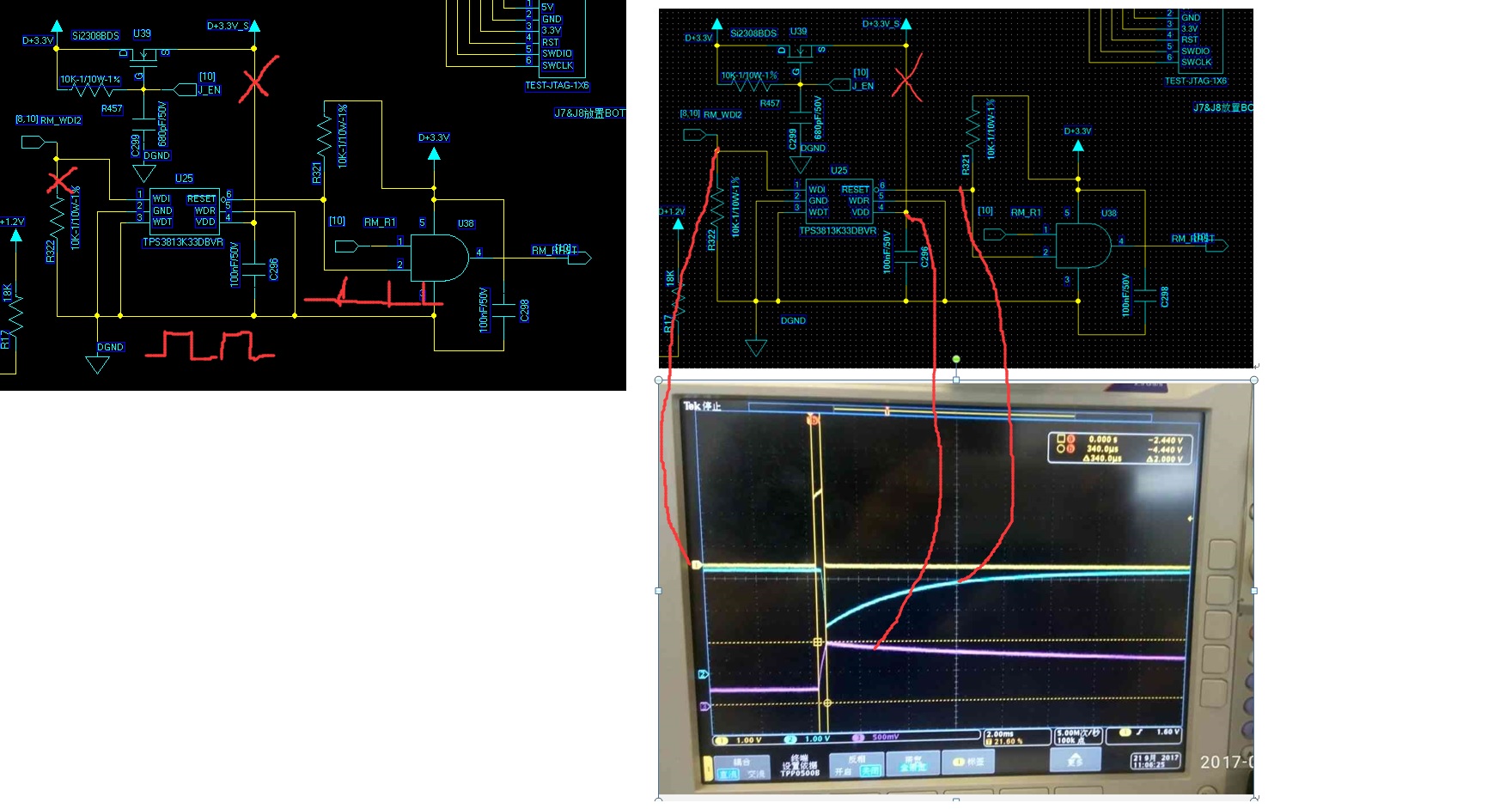
here we meet a issue about TPS3813K33, we found the when the VDD be removed and WDI is normal, then the VDD pin has a similar signal with the same frequency with WDI signal. 

We have verified the chip level test and just apply a signal to WDI and and disconnect with VDD to 3.3V, 

this application scenario is: normally, the WDI is keep running and the RESET will keep high when the VDD is keep 3.3V.

But when the emulator be connected to board, the VDD will be removed at once and WDI will keep running, so we found a signal at VDD/PIN which frequency is almost with WDI signal. 

We have test with only chip level and found the similar issue, you can see below figure. thanks.

Appreciated you can verify at US lab and feedback to us asap. 


Best Regards

Iven Xu

  • Iven Xu,

    The above condition is verified. If VDD is removed, and WDI is still pulsing, the VDD pin can have ringing that matches the signal at WDI.

    Please note the Recommended Operating Conditions table 7.3

    The Input voltage at WDI is recommended to be between and VDD + 0.3V so this means if VDD is removed and 0V then WDI should be ~0V also. The WDI pin should not be above 0.3V higher than VDD or there can be ringing on VDD.

    If there must be active pulsing WDI while VDD is removed, insert pull-down resistor (shown in Figure 8 on page 13) or a decoupling FET with the gate to VDD, source to WDI at device, drain to WDI signal (RM_WDI2) so that the WDI signal will never reach the WDI pin unless VDD is high to turn on FET.

    Please let me know if anything is unclear or have any more questions. Thank you!

    -Michael

  • Hi Michael

    thanks for your work around solution.
    1, so if customer just add a pull down resistor on the WDI pin, then it will work?
    2, or if customer want to add a FET, then they still need to add a pull down resisitor on WDI pin, right?

    Best Regards
    Iven
  • Iven,

    1. Try with only resistor first. Resistor provides easy and quick and cheap solution. Refer to Figure 8 in datasheet.  www.ti.com/.../tps3813.pdf

    2. If resistor doesn't work because of the strength of the signal, the decoupling FET should work in all cases. Try the resistor pull-down solution first and if no success then try FET solution.

    -Michael

  • Hi Michael,

    have verified that it works after add a pull down resistor at the VDD. thanks for your suppor.

    Best Regards

    Iven