This thread has been locked.

If you have a related question, please click the "Ask a related question" button in the top right corner. The newly created question will be automatically linked to this question.

LM5088: Regulation problem at light load

Part Number: LM5088

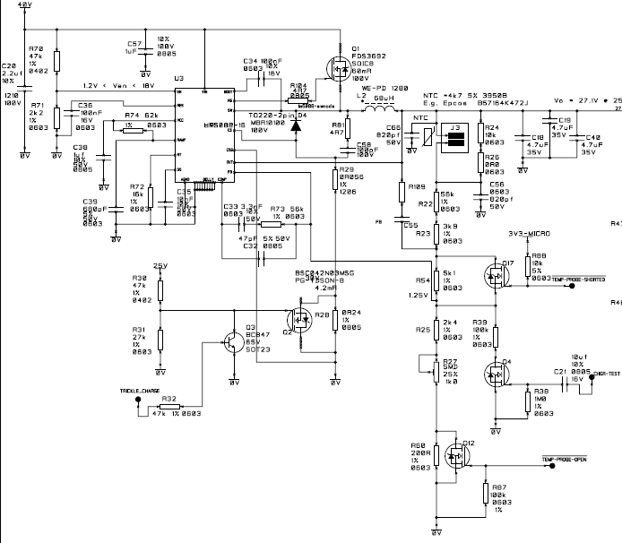
LM5088 Buck converter 27.2V@25°C, Imax 1.4A, fsw ~370KHz

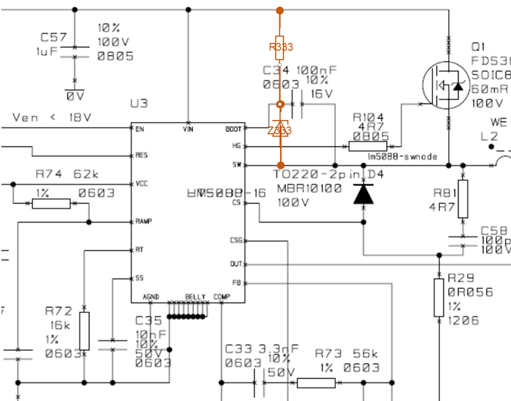
I have a problem with a buck converter used for charging a battery. It seems that when the battery voltage is very close to the charger voltage, the voltage regulation does not operate as expected. The feedback pin remains below the reference voltage. After some investigation I think the problem comes from an insufficient charging of the bootstrap capacitor. When the converter is running dry the regulation is fine and the amplitude of the command is fine.

  • Hello Gilles,

    The LM5088 does have a pre- charge switch internal to make sure the Cboot has adequate charge.  It maybe that the time the pre charge circuit is on, is not adequate to charge the Cboot.  There are two things you can try.


    1.  Decrease Cboot from 100nF to 10nF.

    2. Decrease the buck inductor.


    PS: there does appear to be a lot of switching on the feedback.  You may want to check that the FETs are working and are being programed as expected and not driving the FETs into their linear region?

    Hope this helps?


    Kind regards,


    David.

  • Hello David,

    Thanks for your reply

    • Multiple switching on the feedback:  

    R28, R54, R60 are now shorted and R39 removed => no change detected.

    • Decrease Cboot from 100nF to 10nF (L2 68μH unchanged):

    => it seems that fixed the problem.

    • Decrease the buck inductor L2 from 68μF to 47μF (keeping Cboot 100nF):

    => The problem is not fixed, but the output voltage range for which the feedback seems inoperative has been reduced [27.6V – 26.6V] compared to what it was with the original fit [27.6V – 24V].

    Additional information:

    • The problem is only affecting some units, (Q1 and the LM5088 have been replaced on the faulty unit without any improvement).

    • The problem seems linked to the type of load connected to the output of the charger:

    When connected to an electronic load, the faulty unit works fine and the voltage is held constant for the expected current range [0 – 1.4A].

    When connected to a load similar to a battery, there is a voltage range for which the feedback seems inoperative. When load voltage falls below ~25V the switching resumes and the charger can then properly be loaded. The problem was first spotted on a set of charged batteries and reproduced using the load below:

    I do not understand how this this kind of load could interfere with the feedback.

    Best Regards

    Gilles

  • Hi Gilles,

    Looks like you have a Boot UVLO issue and the Switch is "hanging"  Load will certainly effect the charging of the boot cap because Load in DCM effects the Toff Times. By Toff I mean the time the current slopes negative to 0A.

    If a 10nF cap fixes the issue, I would validate this as a potential solution to the issue.  By Validate, I mean test a number of bad units and see if the reduction in Cboot fixes the issues.  The reduction in Cboot will help charge up the Boot cap well Above the Cboot UVLO for Less Toff times...

    Kind regards,

    David.

  • Hello David,

    After some testing, I realised that reducing Cboot was not the right option.
    I think I have now a better understanding of what the problem is.

    • At some point the battery voltage gets high enough to generate a feedback which causes the converter to stop switching.
    • When the switching is stopped, the charging of Cboot should be made by the pre-charge circuit. Unfortunately, when the battery is connected, it seems the pre-charge circuit fails to pull down the SW pin low enough to properly charge Cboot causing the driver being disabled.

    Could you confirm that is a plausible scenario?
    Could you tell me what would be the best option to keep charging Cboot in this case
    I was thinking adding a resistor and a zener like in the attached schematic.
    Could you tell me if that is a valid option?
    Best regards

    Gilles

  • Hello Gilles,


    Your assessment is correct.  If the output voltage goes above the Set point the converter will stop switching, when it stops switching Cboot will discharge.  I believe your circuit will work provided there is enough Vin head room over vout to Charge the boot cap.  I would make the current very low (uA's) and test to see if this fixes the issue to the needs of your application.

    Regards,

    David.