


Some DC/DC converter data sheets specify using Cff, a feed-forward capacitor (aka, "phase lead capacitor") between the output and the feedback pin in order to improve transient response. In some cases this technique uses a series R-C between VOUT and FB to achieve the same function, but most often I've seen a single cap do the job. Below, I've taken a screenshot from TI's app note involving LDO's and feed-forward capacitors to illustrate this technique.
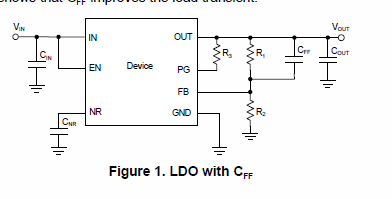
This feed forward capacitor technique is used in both LDO/linear and switching regulators.
In my applications, I am using both LDO's and switching regulators configured as constant-current sources, taking the the feedback signal developed from the [ current X resistance ] of a shunt monitor. For example, to be generic:
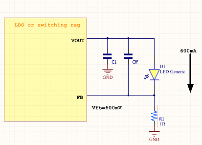
My questions are: (1) When using a regulator as a constant-current source by taking the feedback signal not from the voltage output, but from the [current X resistance] of a shunt monitor, does this affect Cff's value or behavior? (2) Does Cff still perform its duty on transient response if the feedback signal is developed from a sensed current? (3) If the behavior regarding Cff is different between LDO, buck, boost, buck-boost regulators, how so does it differ between these topologies? (4) In constant-current configurations, is Cff still connected between VOUT and FB or is there an alternate connection?
