This thread has been locked.

If you have a related question, please click the "Ask a related question" button in the top right corner. The newly created question will be automatically linked to this question.

LM5106: EN pin toggling

Part Number: LM5106

Champs,

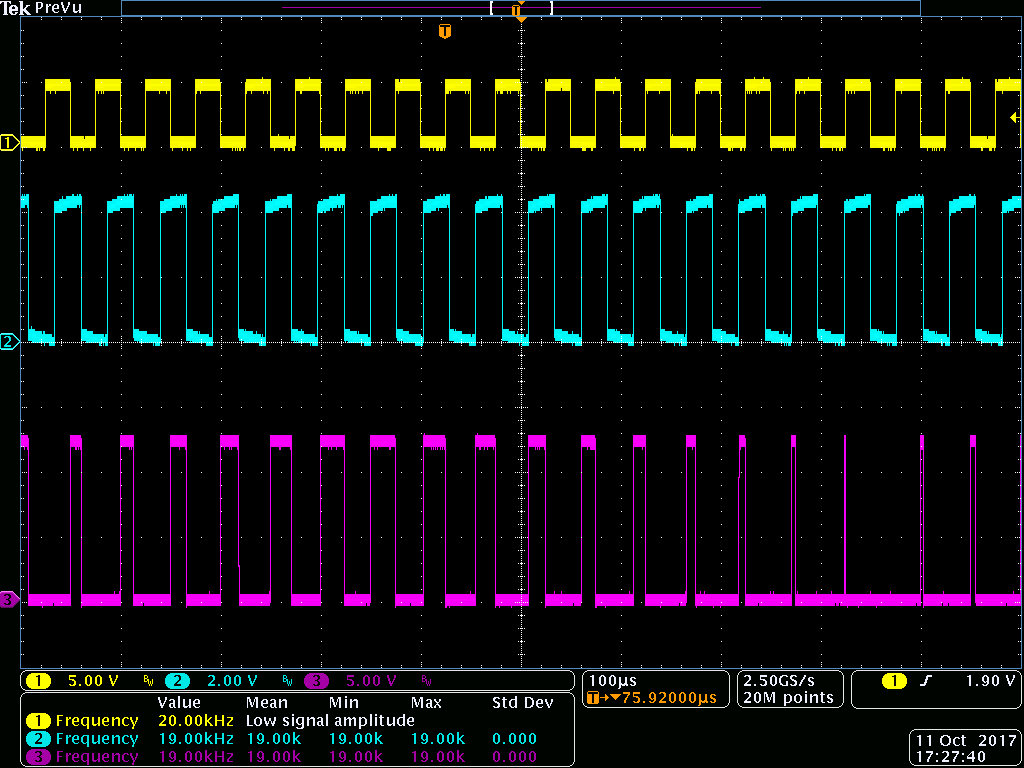
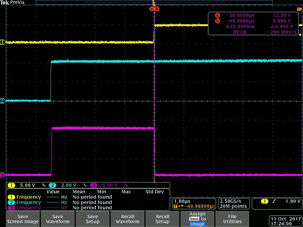
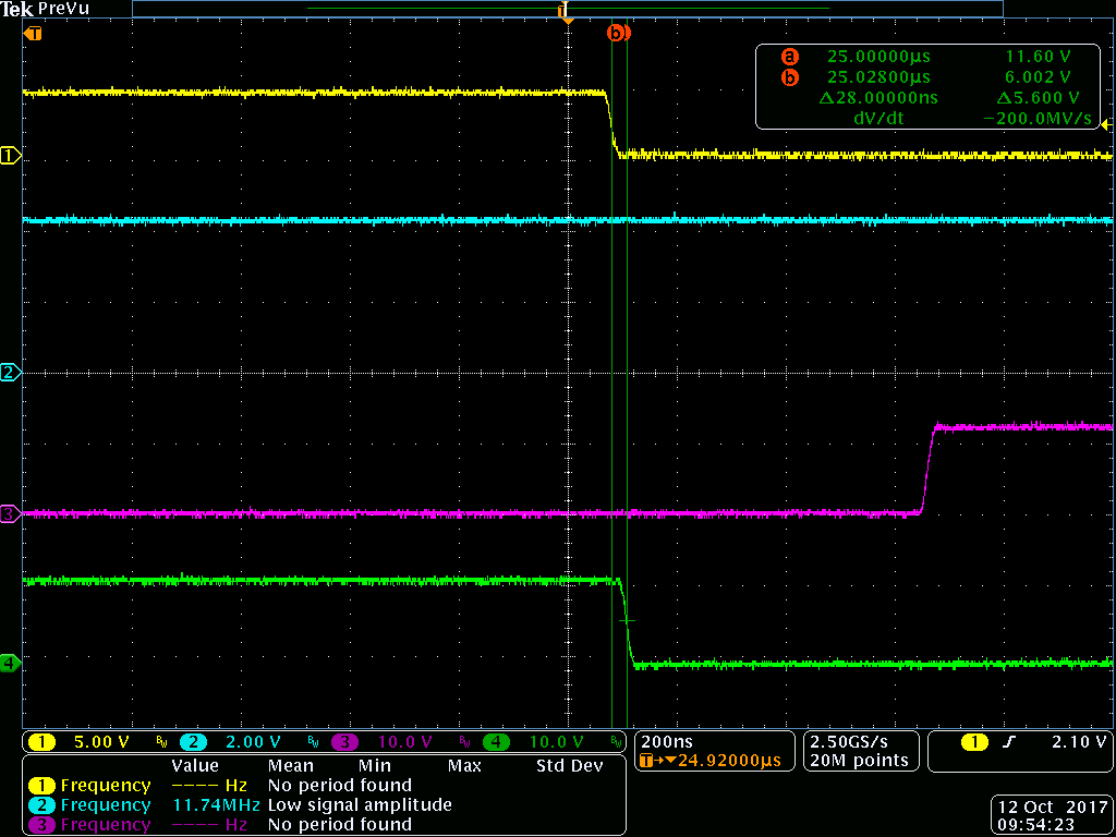
So a question on the EN pin... FUNCTIONALLY it looks like it's just an AND gate to the drivers... but the level shift on the high side and the programmable dead time function has me concerned.  Can the EN pin support a rapidly toggling signal unrelated to/out of phase with the signal at the IN pin?  Or is it intended more as long-term shutdown function that could glitch if given a rapidly toggling signal?  A worst-case example of what I mean would be to input 20 kHz to the IN pin and 19 kHz into the EN pin.  Would the 5106 handle this gracefully?

  • Hi Radar,

    I am an applications engineer for this device.

    My first impressions are yes, the LM5106 can support a rapidly toggling signal unrelated to the input signal but let me verify this behavior on the bench.

    Are you concerned that the operation of the enable pin will fail with an oscillating signal at EN?

    Regards,
    Mateo 

  • Mateo,

    Thanks for the bench verification offer; I think that's what's needed; becuase like you, my initial thoughts were, sure, should work... but...the concern would be this- level shifts are most often implemented with some sort of hysteresis or thresh-hold detect; so if say the PWM input goes high and the high side FET turns on; then infinitesimally later tries to disable the output; does the detect have some lag before the output truly turns off (or more horridly; it’s hopefully not an edge detect and it stays on waiting for a disabled edge that’s now never going to come in).  We’re really mostly concerned that the EN will behave as a real enable- that is, low means output off in all cases.  And I would add; we’d want to know about the low side control too- it’s just for the low side I suspect it’s a ‘real’ gate and thus just works normally; whereas the level shift piece on that high side one is post-gate; and thus introduces the opportunity for squirreliness

  • Radar,

    I have received some samples of the LM5106 and will update you when I take some measurements on the bench.

    regards,
    Mateo

  • Did we find out anything?
  • Hi radar,

    I am working on getting this back to you today!

    Regards,
    Mateo

  • Hi Radar,

    I was able to capture the following waveforms on the bench: [ Channel 1 (yellow): IN, Channel 2 (cyan): EN, and Channel 3 (magenta): LO ]

    I used 100kOhm for R_DT which

    test conditions:

    IN: 20kHz, 50% duty cycle pulse

    EN: 19kHz, 50% duty cycle pulse

    I was able to confirm values from figure 1 in the datasheet despite IN and EN being out of sync.


    regards,
    Mateo

  • Mateo,

    So this piece looks great.... but that's what was expected. What I was chiefly concerned a out as outlined in the initial post was the HI side output; because that's the output with the level shifter. If you could add the fourth channel with the HI side output to the plot I think we'll be there.
  • Hi Radar,

    No problem. The following scope captures are under the same condition but have the 4th  channel (green) connected on HO:
    HPHL measurement:

    t_HPLH measurement:

    DT1 measurement:

    DT2: measurement:

    I hope these scope captures suffice proving the operation with a 20kHz input and a 19kHz signal on the enable.

    Regards,
    Mateo