

Hello everyone!
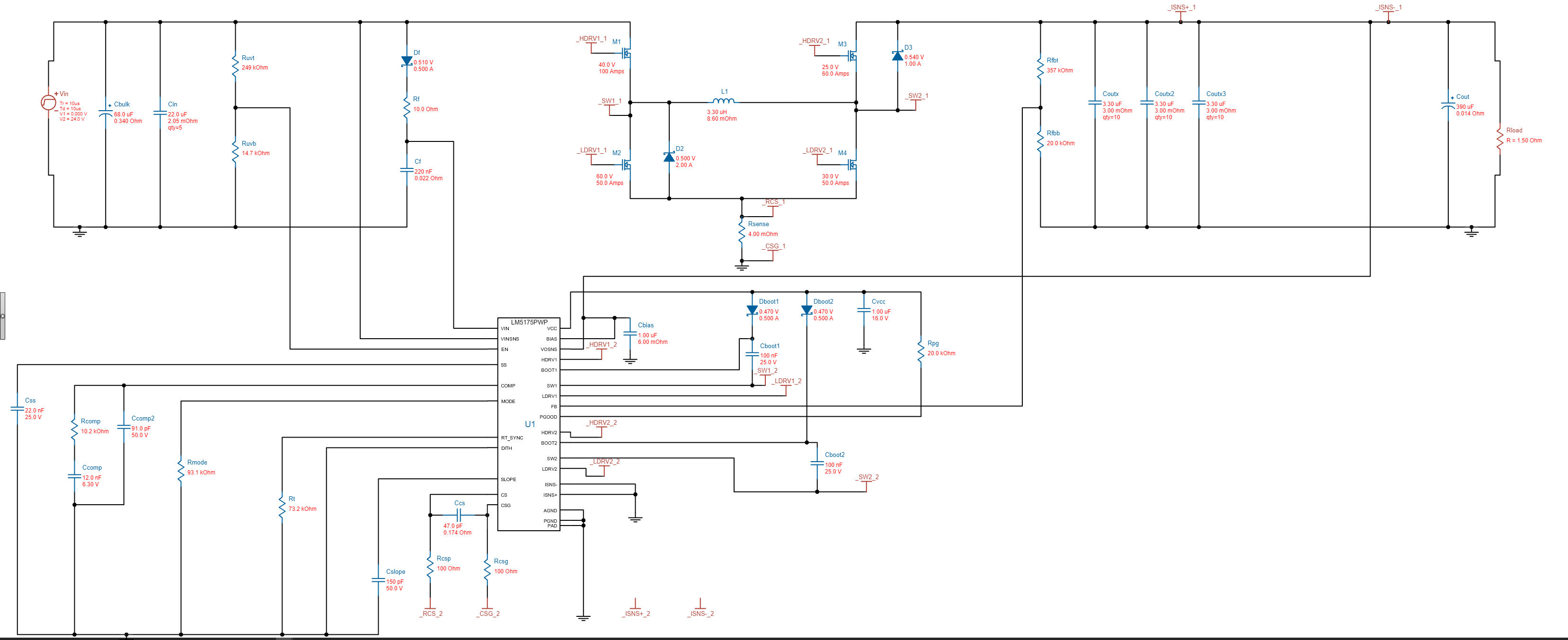
So lately I have been working on a 150W SMPS. It uses the texas instruments LM5175 Buck/boost controller. I used their reference design as a template for my own and I have attached screen caps of both the reference design and my design.
My SMPS specs:
Its supposed to take in 22 - 26v DC and output 0 - 35v DC at 10A (the 10A will only be up to 15v, and at 35v I will Only be able to draw 4A)
I want adjustable voltage and an adjustable current limit.
The problems I'm Having
I have built the circuit on a PCB and it "works" and doesnt blow up, but I have a weird issue where it will only output up to 7.2v DC no matter what I set my feedback pot to. The other oddity is that the lower I put the voltage (3 - 0v) the LM5175 suddenly pulls way more current and it gets VERY hot. At 7.2v It pulls almost no current at all and it only gets slightly warm. The other issue is that I'm not quite sure how to add the adjustable current limit to my design (yes I know I'm a noob at this). My best guess is to add something like a 0.05ohm current sense resistor on the output and then add a potentiometer in line with it to the ISENSE (+) pin on the LM5175 and to connect the ISENSE (-) pin to the other end of the resistor. Here is an ascii image to give you an idea:
________
----(output)----|________|---------(to load)---
| 0.05ohm |
| ---- |
| | _ | ------(to ISENSE -)
500k - > | |
pot |
------(to ISENSE +) ---
So to sum it all up:
I can't go higher than 7v with a 24v input
Anything below 3v makes the LM5175 get very hot
I don't know how to add an adjustable current limit to my design.
If you have any suggestions please let me know! Thanks 
 SMPS V2 Rev6.pdf

-
Ask a related question
What is a related question?A related question is a question created from another question. When the related question is created, it will be automatically linked to the original question.
