Because of the holidays, TI E2E™ design support forum responses will be delayed from Dec. 25 through Jan. 2. Thank you for your patience.

This thread has been locked.

If you have a related question, please click the "Ask a related question" button in the top right corner. The newly created question will be automatically linked to this question.

BATTERY MANAGEMENT SYSTEM

Genius 5355 points
Other Parts Discussed in Thread: BQ76PL455A, BQ76940, BQ78350-R1

Hi Support,

Need your expert advise on the followings.

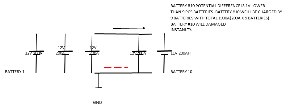
1) The diagram of 10 batteries fully charged by charger. Bit one of the battery #10 has 1V potential difference lower than the rest of 9 batteries.
Battery #10 wiil be charged by batteries of 9 pcc. The current generated of the 9 batteries is 1800A entering battery #10.
The high current 1800A will damaged battery #10 in few seconds.
Please advise solution with TI chips how to prevent battery to battery charging.

2) Am building series and parallel connections of the batteries. Each battery is 50.4V 200AH , connected in 4S 20P.
Please advise TI Battery management IC that function as one master and 20 slaves.
The IC must has active cell balancing, short circuit protection, current limiter of 400A cut off, temperature sensing,
Battery health management, fuel gauge indicator, CAN bus interface and etc.

Thanks.

  • Hi Ikon,
    1. The situation you describe of high inrush current is a common concern in systems where batteries may be paralleled or separated. Normally when using parallel cells the cells are prepared to matching conditions before they are attached, then they function as a single cell with higher capacity.
    Typically the battery circuit monitors the parallel cell group as a single cell. If you have a system where you need to replace individual cells you will need a circuit to accommodate that situation, perhaps switching in the additional cells through a resistive path until the cells are sufficiently matched.
    2. Again the normal battery management system will monitor the 4S pack as if it were single cells. As the number of cells increases, data ranges may require scaling of current or capacity. Most devices will be I2C or SMB interface, so some CAN bus interface would need to be incorporated. However the indication of a 50.4V battery would probably be a 12S battery. If you want to connect 12S (or other) battery modules in series with each having protection switching each should be designed to switch the full stack voltage. If you are monitoring 12 cells the bq76940 would monitor voltage and current, the bq76PL455A would monitor voltage only. The bq78350-R1 gauge is available for the bq76940, but it communicates with SMBus, so you will need a CAN converter. the bq76PL455A could be chained together to communicate cell data back to a common processor where you could gauge your system.
    The active cell balancing solution available is the EMB1428 and EMB1499, see an example in TIDA-00817 to balance to an external supply to balance between modules. TIDA-00239 shows an example of balancing to the module level instead.
    There is not a chipset to provide slave modules with a master controller. The closest to this may be the bq76PL455 for monitoring and active balancing attached like TIDA-00817 with your own custom common circuit for communication, control, current measurement and protection switching.