


Part Number: LM5122
Howdy!
I'm having issues using the TI PMLK PRO to demonstrate how a working BOOST converter works. I am following the lab kit manual (Experiment 13) trying to find the Duty Cycle of the board but cannot seem to get the board to respond correctly.
Details:
- 10 V input from a DC power supply
- Nodes TP10 and TP13 to Osciliscope
- Output Voltage measures at 24 V under no load
- [H3-H8 sh, J13 op, J14 op, J15 op, J18 sh, J19 op, J20 op] || sh: shorted, op: open
PIN Attempts:
- With J15 sh
- With J15 op
- With J16 op
- With J16 sh left side
- With J9 sh
- With J9 op
Load Attempts:
- 5 kOhm
- 400 Ohm
- 300 Ohm
- 200 Ohm
- 100 Ohm
- 50 Ohm
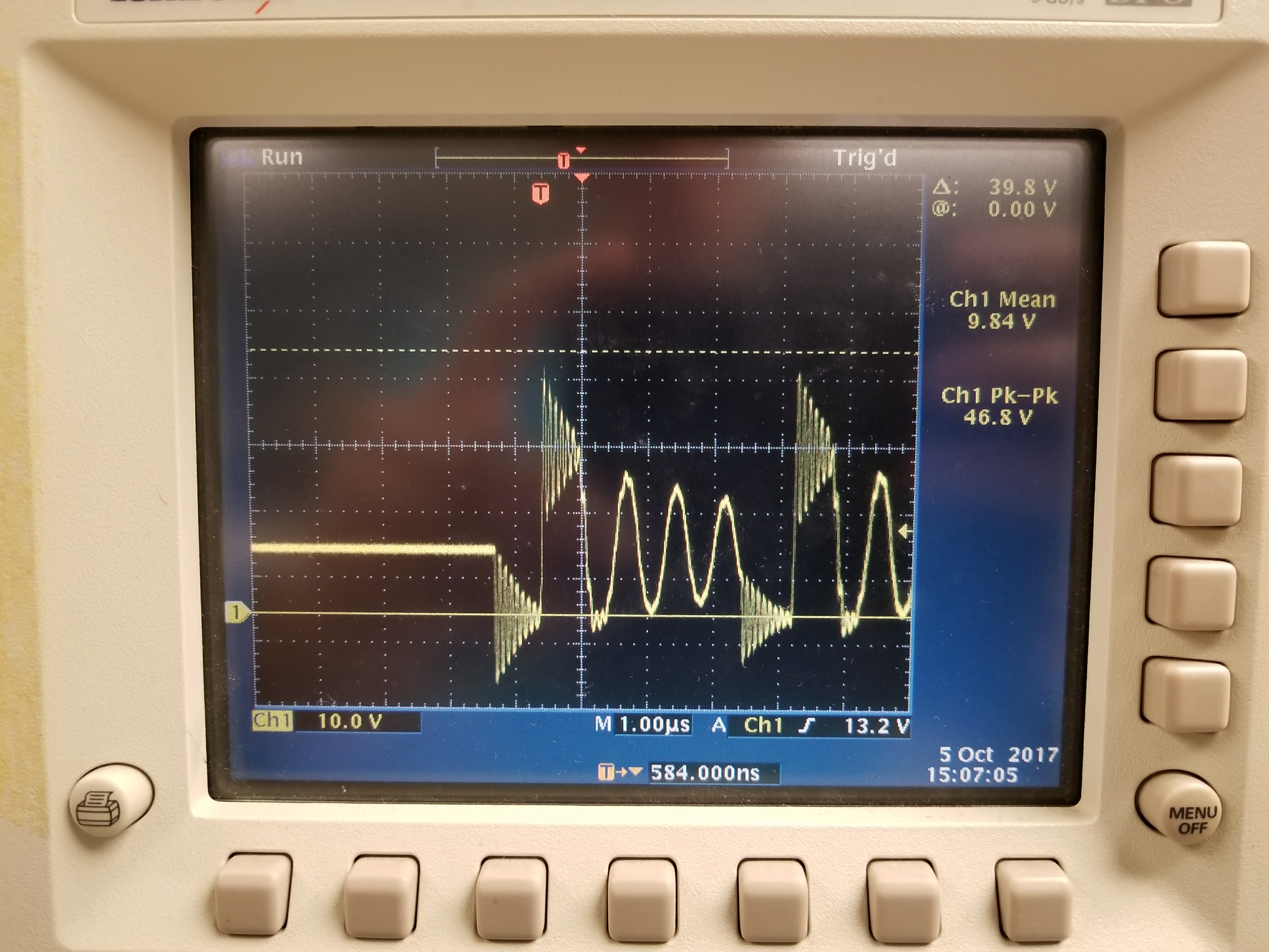
Each attempt results in a garbage signal from the switching node seen by the oscilloscope and a voltage drop from 24 V to around 11 V (15 V for the 400 Ohm attempt). I have followed the lab manual precisely and accurately and cannot seem to get the board to work. How do I get this board to work successfully?
Thanks and Gig'em!
James Van Volkenburgh
Electrical Engineering Undergraduate


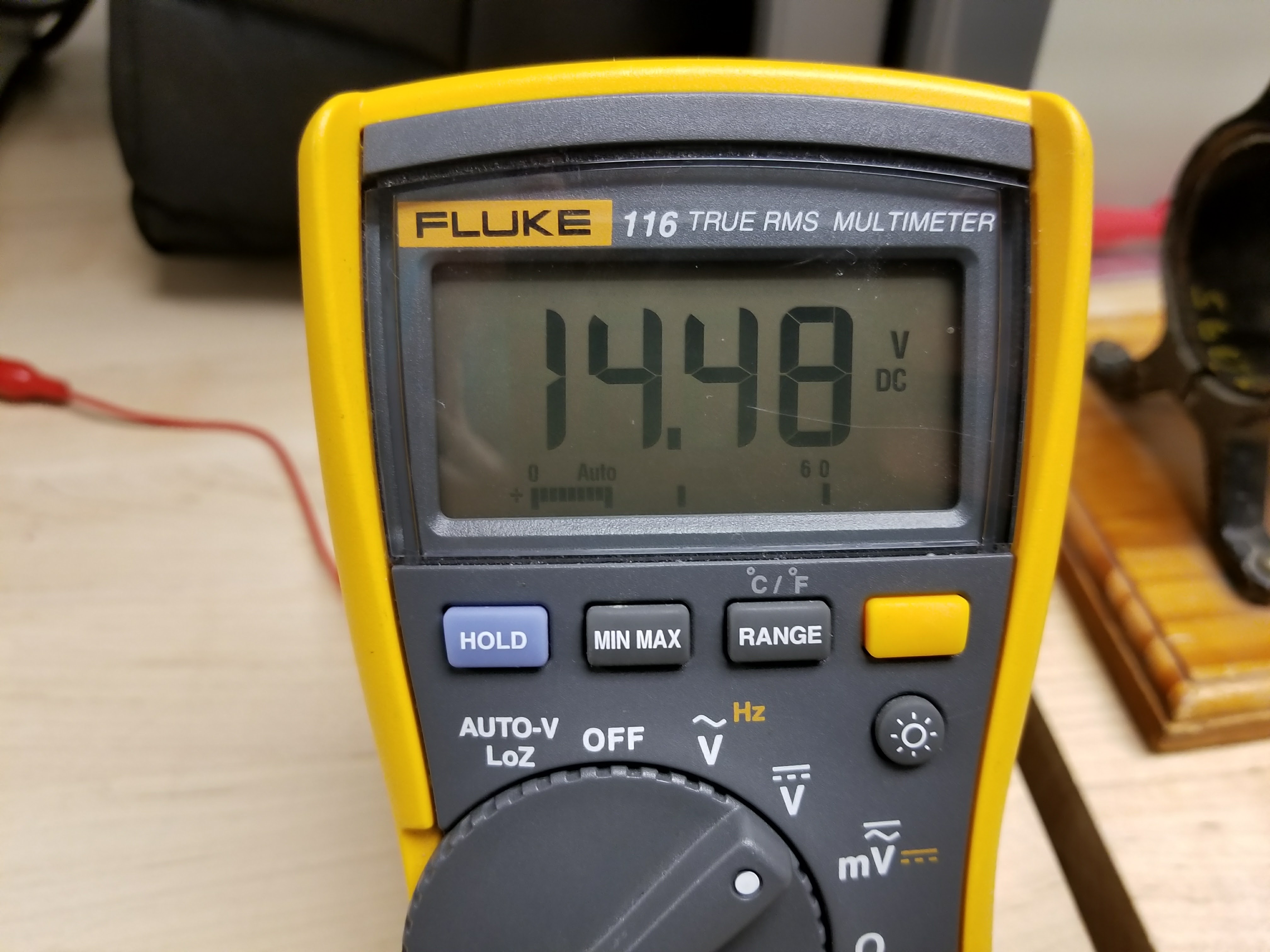
 Here is the Voltage Drop when pulling a load of 200 Ohms
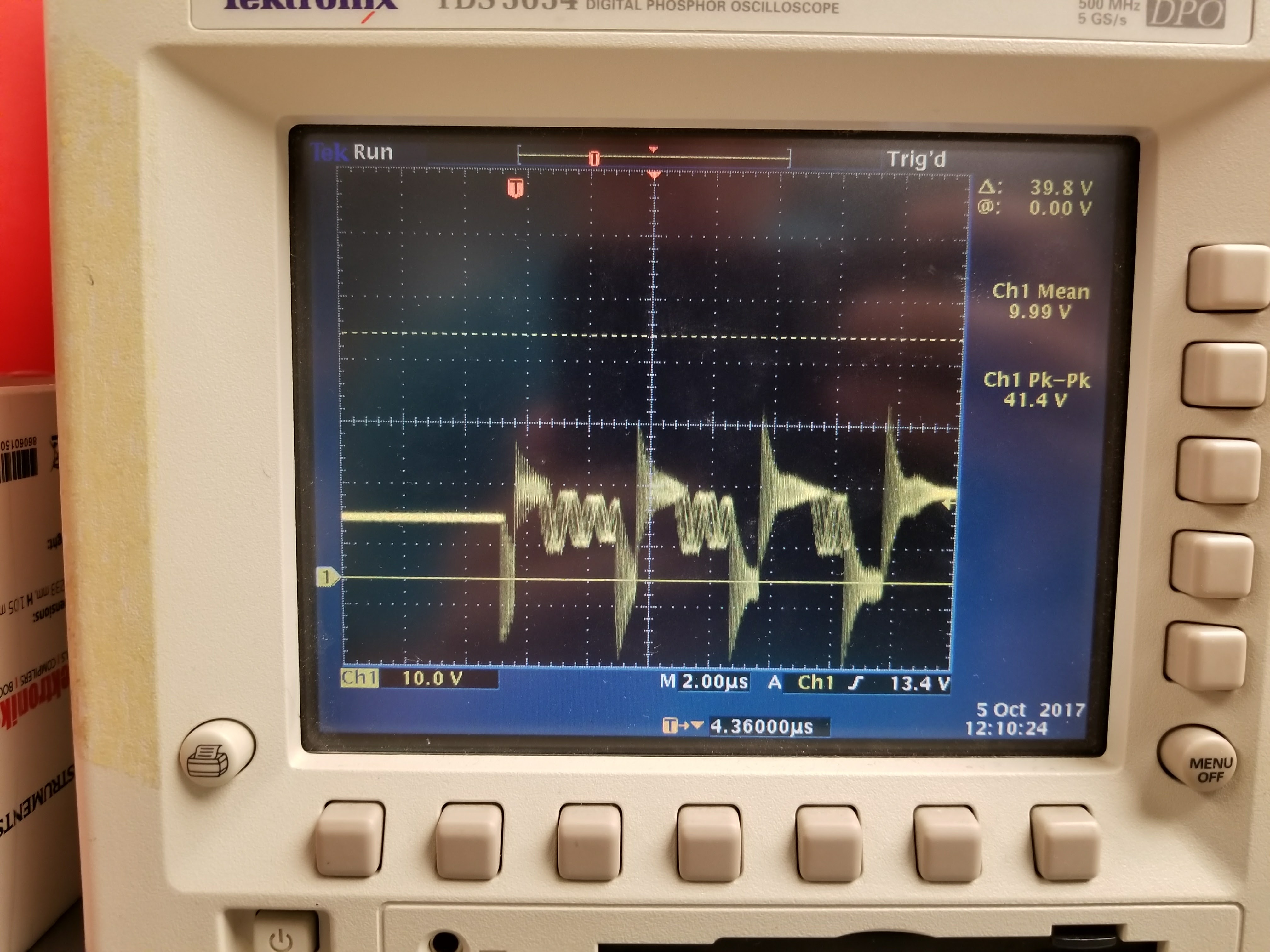
