This thread has been locked.

If you have a related question, please click the "Ask a related question" button in the top right corner. The newly created question will be automatically linked to this question.

TPS53319: Regulator shutting down when output current falls quickly

Part Number: TPS53319

Hello,

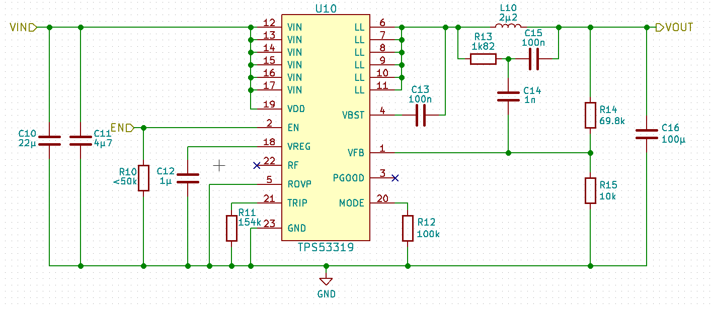
I have a problem with a stepdown circuit based on the TPS53319, which is supposed to generate 5V at max. 10A from 6-19V. The following schematic was copied from Webbench (the component values were verified using the formulas from the datasheet and seem to be correct, C16 is actually 2x 100µF):

The regulator works fine under constant load and a quickly rising output current is no problem, however when the output current quickly falls from some value to a lower value, the regulator switches off.

This can for example be triggered by going from 10A to zero but also when going from just 0.5A to zero or from 1A to 0.3A. Conneccting a 1mF electrolytic capacitor across the output seems to solve the problem, but there is no space for it on the PCB. 

The output voltage looks fine up until the switchoff, with just a little bit of a voltage increase shortly before (should not be enough to trigger the overvoltage protection).

Does anyone have any idea what this could be caused by? Could the layout (not ideal due to space restraints) be the problem, even tho the regulator is working fine at full load?

Thanks and Kind Regards,

Daniel

  • Hi Daniel ,

    Are you using an Electronic load for the evaluation ?
    DO you see the current going negative when you the current falls from let say 3A to 0A . Can you share the load transient waveform .

    If that is the case , i would recommend to change the current level such that the low level transition point is not 0 but some milliamp ie from 3A to 30 mA or so . We have seen some E load causing issue when the transition is to 0A .

    ---Ambreesh
  • Hi Ambreesh,

    thanks for your reply! Unfortunately I only have a very simple DIY electronic load, which does not work well at low currents.

    I did some more tests today and to prevent negative currents, I simply used load resistors connected to the regulator instead of the electronic load. Using resistors I could not replicate the problem, so it seems negative currents might indeed be the problem.

    The intended application of the regulator is to supply some motor drivers which will drive small DC-motors using PWM (1kHz). An interesting thing I noticed today is that running the motor for 1s at 100% duty cycle is no problem, but running it at <100% duty cycle the regulator switches off as soon as the PWM goes to low after the first high-period. This can be seen in the following measurement (yellow is the voltage at one pin of the motor, blue is the regulator output):

    The regulator's output voltage rises to about 5.3V which is below the overvoltage protection limit, but the regulator switches off. Do you know why this happens? When running the motor at 100% duty cycle for 1s the output voltage does not increase when the motor is switched off.

    Kind Regards,

    Daniel

  • Hi Daniel ,

    Does the output recovers to the regulated voltage ? How long does it take to recover ?

    I believe what is going on here is that the Motor being the inductive load is acting as a source when the PWM goes low and causing reverse current to flow . You can visualize the system as reverse Boost .
    You can verify the same by monitoring the inductor current at PWM on to off transition .

    Further you should be able to block the reverse current flow by adding a diode or a PFET or a NFET with high side driver at the output . Just to start you can add one high current diode at the output and verify if you are still facing output shutdown issue .

    ---Ambreesh
  • Hi Ambreesh,

    the output does not recover, the regulator stays switched off until the input power is switched off and on again. Setting the enable line to low might also restart the regulator, but I haven't tried that yet.
    I will follow your suggestion and will try it with a diode to stop reverse currents. However, it would be nice if there would be a simpler solution (a diode is simple of cause, but the power loss would not be great) for the final application. Is there any other way to make the regulator immune to reverse currents?

    Kind Regards,
    Daniel

    EDIT: The diode prevents the shutdown, so I think it is clear that the issue is caused by reverse currents. But how exactly do they affect the regulator? As long as the voltage of the output stays below 120% of the target voltage, the regulator should not care, right?

    Thanks for the help so far!

  • Hi,

    I did some more measurements to understand why the regulator switches off and this one shows that the voltage at the feedback pin does actually reach a value above 120% of the 0.6V target voltage even tho the output does not (the blue trace is the output voltage, the yellow trace is the feedback voltage. The solid voltage-cursor is at 720mV which is the 120% limit which the feedback voltage exceeds):

    I suspect that the proportionally larger rise in the feedback voltage is caused by the ripple injection network, which AC-couples the voltage increase from the output to the feedback pin. So maybe the problem could be avoided by not using the network, and use an sp-cap instead of a ceramic one to keep the regulator stable. Doing this, the feedback voltage should only reach more than 120% of the target when the output voltage is also over 120% of the target, which could be prevented using a ~5.6V zener or tvs diode.

    Do you think that would be a possible solution?

    Kind Regards,

    Daniel

  • Hi Daniel ,

    The negative current limit would indeed limit the reverse current and thereby limit the rise in voltage .

    One thing you may want to optimize is amount of ripple being fed to FB by changing ripple injection circuit R13 and C15 . For more details please follow the app note www.ti.com/.../snva166a.pdf .

    ----Ambreesh