This thread has been locked.

If you have a related question, please click the "Ask a related question" button in the top right corner. The newly created question will be automatically linked to this question.

WEBENCH® Tools/LM25118: Output problem

Part Number: LM25118


Tool/software: WEBENCH® Design Tools

Hoi guys,

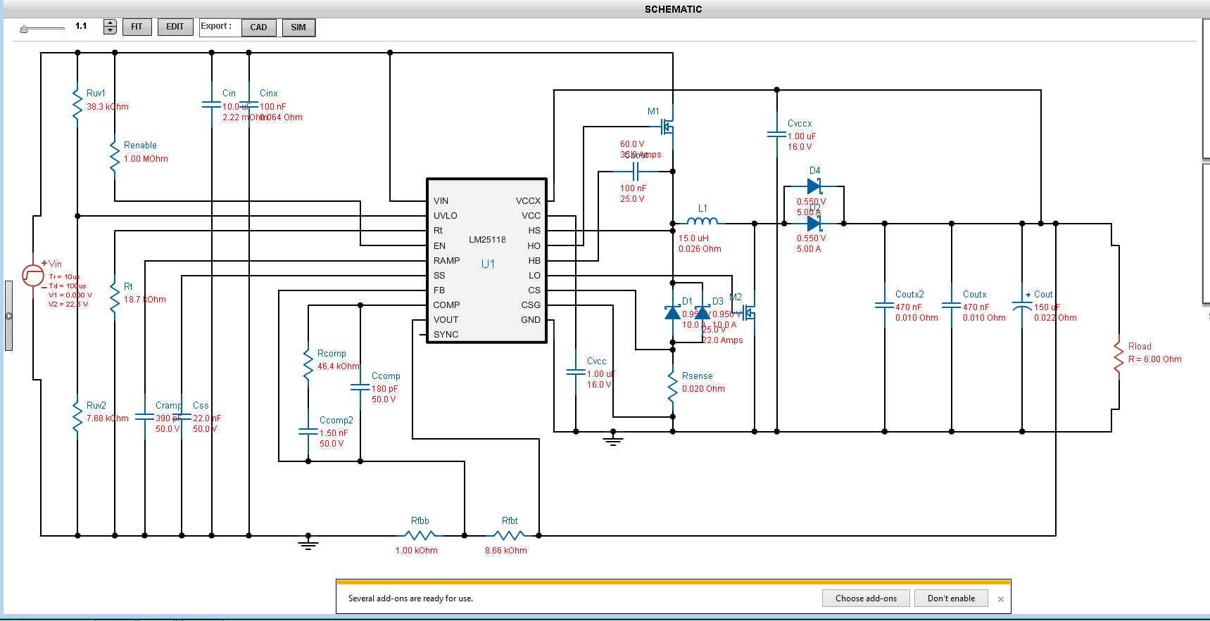
For my school project I have used the LM25118 to convert 9-36 VDC to 12 VDC 2A. With the help of Webench I have built a circuit. But it doesn't work as I hoped.

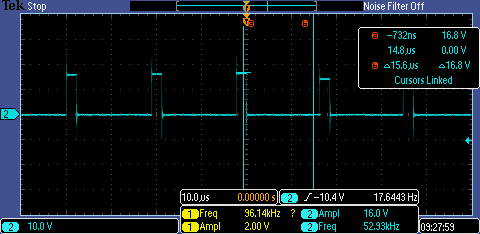
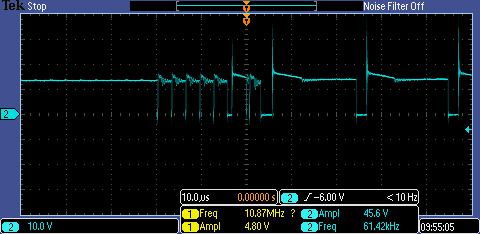
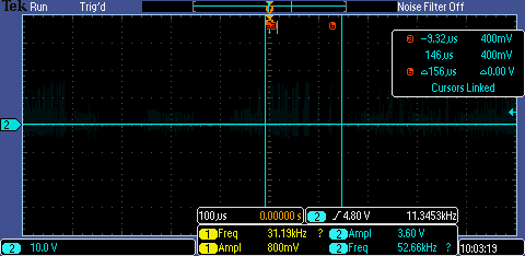
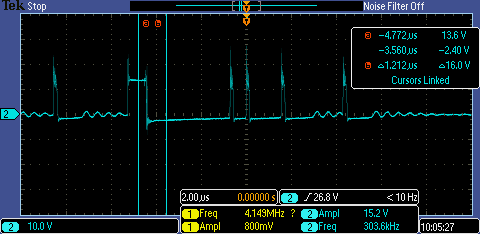
When the input was 14 VDC, first the voltage at the negatief side of the conductor (V_conductot_ground) was 12 VDC(square wave). But when I tried to measure the output voltage, I don't get 12 VDC but a strange signal.  the output voltage was less dan 1 V DC. After that I have measured the V_conductor_ground) again but the square wave of 12 VDC is gone, in place of that is a strange signal. Can someone explain me why?.

I have used the circuit below and the VCCX is connect with the ground.

  • Hi
    Would you please post some waveforms for better understanding of the issue ? What is V_conductot_ground ? What is V_conductor_ground ?
    The engineer in charge of this device is out of the office now, he will be back in the office next week
    Regards,
    EL
  • Hoi EL,

    I apologize for the type fout that I have made. I mean V_inductor-ground. I have found out today that de IC is damaged. That is de reason for the strange signal which I have seen yesterday.

    However I can't get the right output voltage when the IC is replaced. En why is the switch frequentie of the mosfet not 300 kHz?

    Below is soms waveforms that I have measured with the new IC.

    Foto 1 is de V_GS of the buck mosfet when input is 14 VDC.

    Foto 2 is the V_DS of the buck mosfet when input is 14 VDC.

    Foto 3 is the output when the input is 14 VDC.

    Foto 4 is the V_inductor_ground for 14 VDC input.

    Best regards,

    HT

  • the measurements are made with no load. I have forgotten to tell u in the last reply
  • Hi Hao,

    The WEBENCH design looks okay. How are you actually building the converter? Is the layout done following the guidelines in the datasheet? Something might be connected incorrectly on your board?

    Thanks,

    Garrett