This thread has been locked.

If you have a related question, please click the "Ask a related question" button in the top right corner. The newly created question will be automatically linked to this question.

BQ76940: TIDA-00792 Sleep and Wake-up Circuit

Part Number: BQ76940
Other Parts Discussed in Thread: TIDA-00792

Hi guys,

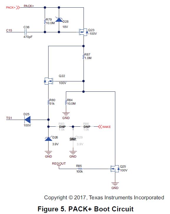
I am looking for a solution booting the BQ76940 automatically when a fuse, placed in pack+ line, is closed to power all sub-systems. (The fuse is like a on/off switch for the whole system)

Therefor I checked out the TIDA-00792 design and was wondering if section 2.2.8 provides this solution. As far as I understand TS1 gets a signal as soon as pack+ is powered on, and also can a signal be sent over WAKE (e.g. from a microcontroller) to boot the device, is this correct?

  • Hi Daniel,
    Yes. The purpose of the circuit was to boot the bq76940 when the charger was applied after the system had been off with PACK+ low. That feature would be useful where the charger would apply its main voltage to start. The un-populated WAKE components were an option to wake the pack from an external PACK- referenced signal. This may be useful in a system where the charger would apply a wake up logic or higher voltage pulse signal before turning on its charge voltage.
    Certainly both could be built into a design or the circuit modified to provide boot with slightly different signaling. Do remember that the bq769x0 boots from a rising edge on TS1, a constant high will not prevent shutdown or cause a wakeup immediately after shutdown.
  • So basically speaking: If I put voltage on Pack+ TS1 is activated right?

    Then I could modify the circuit to have a trigger from my microcontroller, like in this picture. Would this work?

  • Hi Daniel,

    I think it is more correct to say if PACK+ is ramping with respect to battery+ then TS1 will be applied.  The circuit is explained in the design guide for TIDA-00792 section 2.2.8.  

    I'm not sure if your circuit will do what you want.   If the microcontroller is off the FET is a diode and boot should work.  If the MCU is on,  the FET could be enhanced, but unless PACK+ was ramping toggling the GPIO would not help.  If you reverse the FET then the MCU could prevent the boot by setting GPIO low, but could not induce it without the PACK+ ramping. If your microcontroller is powered separately from REGOUT and you wish to boot the bq76940, you might use the GPIO through a diode to TS1 for boot.  If the microcontroller is 5V, you might need to limit the voltage before sending to TS1 similar to figure 4 of the design guide, that is consider connecting the GPIO to WAKE.

  • Right, I forgot about the ramps. So this should work I think: When Pack+ is ramping, TS1 will be applied. To reboot I now can block the voltage by setting GPIO1 low, shutting the FET off. Then, via GPIO2, I can send a ramp to TS1 as often as I want to. Or do I still have a mistake in that idea?

  • Hi Daniel,
    I think that will work.
  • I still have one question: Why is there a 100V diode in front of TS1? Only 3.6V max are allowed, so why is this oversized?
  • Hi Daniel,
    D25 is used to prevent the temperature measurement from being affected by the boot circuit load.
    D25 or similar diode does not need to be a high voltage diode since the reverse voltage must be low due to the low abs max of TS1. However the diode was available in the design and using another avoided a separate BOM item.
  • Oh ok. So to achive the necessary voltage at TS1 the MOSFETs Q22 and Q23 are used (as source follower as far as I understand)?
  • Yes, basically.