This thread has been locked.

If you have a related question, please click the "Ask a related question" button in the top right corner. The newly created question will be automatically linked to this question.

TPS92515-Q1: Clarity on UVLO and PWM pin

Part Number: TPS92515-Q1

Hi Team,

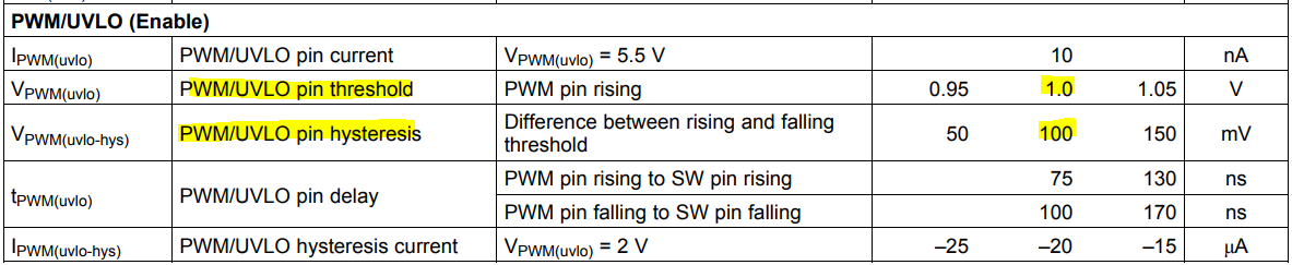
I am reading through the TPS92515-Q1 datasheet, section 8.3.11. In section 8.3.11.1, it details how to apply a PWM signal to the PWM pin for dimming. Then, in section 8.3.11.1, it sounds like the PWM pin can be used either as a PWM input for dimming OR to adjust the hysteresis on UVLO level.. am I understanding that correctly? If not, can you please explain? If yes, then I can apply a PWM signal to that pin for dimming and adjust the UVLO levels at the same time?

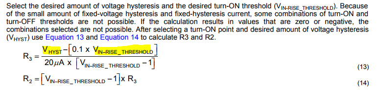
In section 8.3.11.1.1, it explains how the resistor divider sets the UVLO lockout level, and section 8.3.11.3 explains that there are three pins where UVLO levels are applicable. Does the change in UVLO level due to resistors as described in section 8.3.11.1 cause a change in UVLO on all 3 pins? If not, where is the change in UVLO with the resistors applied?

Thank you in advance for the help!

Jared

  • Hello Jared,

    You can use the PWM pin to set a UVLO and PWM dim at the same time if you like. You just need to diode OR in the PWM signal by tying the anode of a schottky to the PWM pin and apply the signal to the cathode, or you can use a FET from PWM pin to ground and drive the gate of the FET with your PWM signal. You set the UVLO the same way as without PWM dimming.

    The UVLO setting using the PWM pin is independent. No matter what you set it to the BOOT and VCC UVLO levels are always set to the value given in the electrical characteristics. I hope that helps.

    Regards,

    Clint

  • Hi Clint,

    Thank you for the support! Since the BOOT and VCC UVLO levels are at a fixed value, does that mean that adjusting the UVLO level with the resistors will affect the UVLO of VIN?

    Thank you,

    Jared

  • Hello Jared,

    The PWM pin UVLO using the resistors is a UVLO setting for the input voltage VIN only really. If you set it below the VCC UVLO then it will do nothing and VCC UVLO will be dominant. If you set it above VCC UVLO then the VIN UVLO will be dominant. The part will be alive above the VCC UVLO but it will not start switching until the VIN UVLO you set with PWM is crossed.

    BOOT UVLO is really just a protection mechanism during operation. BOOT will not even charge until both VCC UVLO and the PWM threshold are both crossed. Then it will charge and the part will start switching once BOOT is charged past its UVLO level. Does that make sense or did I just confuse you? Thanks.

    Regards,

    Clint

  • Hi Clint,

    Makes sense to me! So then looking at the two equations to determine R3 and R2, there are two variables that it seems the user can choose values for, those being Vhyst and Vin-rise_threshold.

    But in the electrical specs, it seems those two variables are already spec'd..

    So does the user setting override the default threshold and hysteresis in the electrical specs? Or does the user selection need to fall within the min and max of these specs?

    Thanks!

    Jared

  • Hi Jared,

    The value in the EC table is for when you are driving PWM directly with no UVLO resistors. The hysteresis comes from the 20uA source being turned on and flowing across the 5k internal resistor (5k*20uA = 100mV)..

    If you use UVLO resistors the hysteresis will always be higher than 100mV so it will override the 100mV spec in the EC table. The 20uA hysteresis current will be going through much more resistance. So when using the UVLO function with the PWM pin that EC table spec becomes a non factor.

    Regards,

    Clint

  • Hi Clint,

    Thank you for your detailed responses, very helpful! Sorry for the slew of questions, but just to complete my understanding, why would a user want to select their own UVLO setting? What sort of reasonable UVLO settings would a user target if they are deviating from the default UVLO level?

    Thanks again for the help!

    Jared

  • Hello Jared,

    That question made me realize I was wrong about something I said. BOOT will charge with VCC rather than wait for the PWM threshold.

    That being said, the reason you want to set it higher is so that the converter can operate correctly without any strange transients. If you have an LED stack of 15V but you do not set UVLO with the PWM pin the part will start trying to switch when VIN is lower than the LED stack voltage. If the VIN rise is very fast this may not be an issue. But if it isn't very fast the switch will turn on and stay on trying to reach the peak current sense threshold. However, it can't reach it because VIN is lower than Vout so the switch stays on until BOOT discharges. You can get an oscillation as it goes in and out of BOOT UVLO. So although it isn't really necessary in any case if you set the UVLO via the PWM pin to above the LED stack voltage it will start off and operate smoothly every time regardless of input rise time.

    Regards,

    Clint

  • Hi Clint,

    That makes sense. So looking at equation 13 and 14, you would want to set the Vin-rise_threshold to above your LED stack max voltage, correct? And then for Vhyst, I am assuming this value will become larger as your Vin-rise_threshold value increases, correct?

    Thank you so much for helping me out with this information!

    Jared

  • Hello Jared,

    The max LED stack voltage is the minimum you would want to set it at ideally. But really the input voltage range is the determining factor. UVLO is there to help protect the input supply as much as anything else. So generally you would set it just below the minimum input voltage you would expect. Then the hysteresis is sort of dependent upon the application. You usually want at least 2V of hysteresis or so, but if you expect input voltage dips in your system you might want more so that it continues to run through them. Ideally the shutoff point is still above the max LED stack voltage, but that isn't necessary after startup as long as you don't mind the LED current decreasing at some point.

    Regards,

    Clint

  • Thanks Clint! Fantastic support!