This thread has been locked.

If you have a related question, please click the "Ask a related question" button in the top right corner. The newly created question will be automatically linked to this question.

BQ24160: Grounding D+ and D- pins

Part Number: BQ24160

In my application I am not using D+/D- detection and I set the USB current limit via I2C. In my previous prototype I left D+ and D- pins floating and it worked fine. What will happen if I connect both D+ and D- pins to PGND? Will this cause any electrical problems (short circuits, noise, oscillations..) and what state will be detected?

I am considering this option in order to add another route under D+ and and D- pins from thermal pad and PGND pins to vias toward ground plane (I had some problems with ground bounce in my previous design...)

Valentin

  • Valentin,

    With D-=D+=GND, SDP will be detected, setting current limit 100mA. Most people connect D+=D- to set input current limit to the higher default value.
  • Thanks Jeff,

    that was also my understanding, but I preferred to check in order to avoid a malfunctioning prototype board.
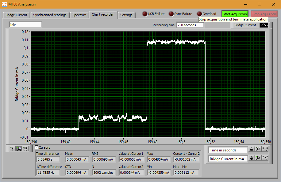
  • As a follow-up, I was able to measure and record the current from the D+/D- pins on my bq24160EVM board. Maybe someone else would found them interesting, so I attached the two screenshots with the results. Detection is performed only once when USB voltage input is attached and bq24160 is in DEFAULT mode (or triggered manually by setting a D+/D-_EN bit). Detection takes about 85 ms. If D+ and D- is shorted and both are connected to GND, the current towards GND is about 1.4 mA for approximately 40 ms, which I found to be acceptable.

    Current between the D+ and D- (D+ and D- shorted with a mA-meter, but not connected to ground, 1.5 A limit was selected):

    Current between shorted D+/D- and GND (100 mA limit was selected):