This thread has been locked.

If you have a related question, please click the "Ask a related question" button in the top right corner. The newly created question will be automatically linked to this question.

UCC28740: transformer

Part Number: UCC28740

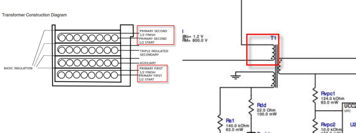
any body have suggestion the mean if bellow transformer construction (left picture) it construction the primary winding divided by 2 (first half & second half) so it will has 4 terminals but if we check at the schematic diagram the primary winding just 2 terminals, so how to install that transformer to the circuit ?

is it the finish of first 1/2 connected to the start of second 1/2 ? or how

thanks

  • Hello Kurni,

    Thank you for your interest in the UCC28740 and transformer construction.

    You are correct, for windings which are split into two halves (with other windings placed between them) the finish of the first half is connected to the start of the second half. This connection is often done at an un-used pin that may not be shown in the schematic diagram. The diagram shown 2 pins for the primary and a third pin is used to terminate the first half to make it easy to add the other windings over it, then the second half starts at that 3rd pin and finishes at the 2nd pin shown on the schematic.

    Sometimes this intermediate pin is shown on the schematic. Sometimes, the connection is made without a third pin, but simply soldering the 2 halves together and insulating with heat-shrink sleeving. This pin-less connection is more difficult to handle during transformer winding, so it is not often done. The 3rd-pin technique is most often done, whether that pin is shown on the schematic or not. This technique is not limited to primary windings, of course, and applies to any number of other windings that are split for to reduce leakage inductance, ac-resistance, EMI-noise cancellation or other reasons.

    Regards,
    Ulrich
  • Hi Ulrich

    Thanks your quick answer

  • Hi Ulrich

    1 more question, about detail winding process, if i want the pin configuration like above picture

    1. so i must start winding the primary first 1/2 at pin 1 and finish at pin 2 right ?

    2. for auxiliary winding which pin  start & finish ?

    3. for secondary winding which pin  start & finish  ?

    4. then for primary second 1/2 must be start winding at pin 2 and finish at pin 3 right ?

    many thanks

    Kurnia

  • Hello Kurnia,

    Let us designate the “+” ends of each winding to correspond to the “dot” polarity marks of the transformer schematic drawing.

    To match the pin assignment shown and the winding direction instructions given (clockwise, counter-clockwise):

    1. Start first-half primary at pin 1, wind clockwise, finish at pin 2

    2. Start auxiliary winding at pin 4, wind counter-clockwise, finish at pin 5

    3. Start secondary winding at pins 9&10, wind counter-clockwise, finish at pins 7&8

    4. Start second-half primary at pin 2, wind clockwise, finish at pin 3

    That should give you the voltage polarities at the pin numbers shown.

    Regards,
    Ulrich

  • Hi Ulrich

    Many thanks

  • Hi Ulrich

    i have more question about bellow transformer construction:

    Base on above transformer report, the secondary winding has 7 Strands by using 25 AWG, and the Coil former is  EF20 type, i have try to order to the transformer factory , but they said the secondary winding is too big to assembly with Coil former EF20

    So, my question is: can i reduce the size of wire for secondary winding ?, what is the minimal size

    The my design output power is : 3.3 VDC, 3.3A

    Many thanks