This thread has been locked.

If you have a related question, please click the "Ask a related question" button in the top right corner. The newly created question will be automatically linked to this question.

BQ2970: Battery protection external to the Battery Pack - required

Part Number: BQ2970
Other Parts Discussed in Thread: BQ24314

Hi,

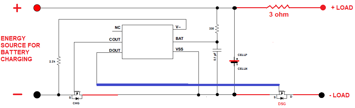
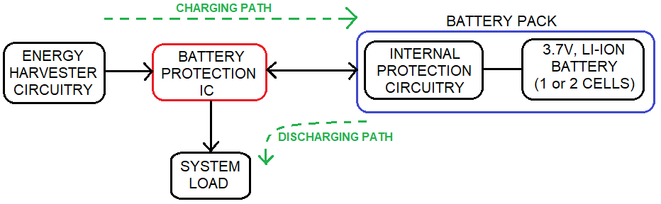
I am designing a charge controller for usage in Energy Harvesting applications. This charge controller takes power from the solar panel, and charges 3.7V, Li-Ion battery pack (either 1 or 2 cells depending on energy rating requirement). I am pursuing suitable energy harvester ICs that can work with Solar power, but there is no adequate Battery protection mechanisms like over-charge, over-discharge, over-current, short circuit, etc. So, I am thinking of using a companion protection IC like BQ2970 that can provide good protections. For easy understanding, I have attached the block diagram of the intended charge controlling application. Battery Pack has in-built protections already, but they are also not adequate. Battery pack is provided by an external vendor, that I don't have much control on it. So, I want to provide protection circuitry external to the battery pack as well.

I have gone through BQ2970 (and its series), but there are some issues with it as below.

  1. I need over-charge protection of 4.2V for my Li-Ion battery, whereas BQ2970 has 4.275V min. 3.85V for BQ29706 is much lower than the required 4.2V.
  2. BQ2970 is actually meant for protection within the battery pack. However I need protection external to the battery pack. Kindly check below attached block diagram.
  3. BQ2970 requires external MOSFETs. Our preference is having internal MOSFETs, though this is not a hard requirement.
  4. BQ2970 does not seem to fit the protection requirement as per the below intended application (in the block diagram).
  5. BQ29700 has Over-discharge cut-off voltage of 2.8V. Once it has cut-off at this voltage, the battery will get charged again based on the solar power. Once it charges to ~3.7V, we want to connect the battery to the load again. I am terming this as Load Re-connect voltage. Such Load re-connect mechanism is not there in BQ2970.
  6. We want the IC to have charging/discharging ratings up to at least 0.5A.

Can you suggest any suitable IC that can resolve above issues?

Thanks & Regards,

Vikas Chandra Rao.

  • The bq2970 is not meant to work outside of the battery pack, and we don't really have a good solution here. You could try looking into using the bq24314 or one of those devices. They are meant to be placed inbetween an AC/DC wall adapter and a charger. Not certain it will work for your application, but perhaps take a look at it.
  • Hi,

    I don't think I can use BQ24314 for my needs. I was just thinking whether I can use BQ2970 itself in below configuration. Can you check the below connection diagram, and let me know whether I can use BQ2970 for protection of the Battery, and at the same time provide a discharge path from battery to the load appropriately? I think I may lose the Over-discharge current limiting feature with this connection, but I have added a 3ohm resistor for limiting the current (to 1A approx). Will I lose any other functionality by this connection. Kindly suggest if I need to do any modifications in the connection, so that I can get appropriate needed protections.

    Regards,

    Vikas Chandra Rao.

  • I don't think this will work as you have a short that can happen to the right if the load is somehow shorted. You will limit the current but no DSG FET will go off as the bq297 measures across V- and Vss to look at the current threshold and you will only have CHG across V- and VSS.
  • Hi,

    Yes, the short circuit on the load side is also a problem with the above connection diagram that I sent you on 01/Nov. Is there any other problem with the above diagram?

    Will the below connection diagram be better than the above one? In this case, the short circuit current may be lowered by half because short circuit current flows through DSG FET only. But I am fine in having half of the short circuit current, like 5A in place of 10A. I am fine in selecting SCP voltage of 0.3V instead of 0.6V or so. Or I am ready to have different FETs (with different Rds) on CHG and DSG. I may be wrong here in letting you know the values, but I am ready to compromise on the short circuit current value, instead of not having the protection at all. Kindly clarify, and suggest if I have to make any further modifications here to get appropriate short circuit protection.

    Are there any other problems with the below diagram?

    I have few basic doubts about BQ2970 as below. Can you clarify the same?

    1. Both the Charge Over-current and Discharge over-current are measured using the same voltage drop between V- and VSS. If both charging and discharging happens simultaneously, how can it distinguish both these fault conditions?
    2. If CHG MOSFET is off due to a fault condition, how are the PACK terminals connected to the CELL terminals for discharging path? Similarly, how does it work for vice-versa (DSG FET off and connection between terminals for charging path).
    3. There is a caution in section 9.4.1 of the datasheet. "When the battery is connected for the first time, the discharging circuit might not be enabled. In this case, short the V– pin to the VSS pin. Alternatively, connect the charger between the Pack+ and Pack– terminals in the system". In the production environment, we can connect a charger between Pack terminals to overcome the above situation. So, once it is enabled, we take it to the field. However we may not connect Battery to the Load until installation is done.
      1. Is this process of connecting battery terminals to the load during the installation fine?
      2. Will the battery get depleted because of BQ2970, from the production time till installation? How much will it deplete? Will it be based on 5.5uA or 0.1uA?
      3. What does current sink of 24uA on V- mean? How much power does BQ2970 circuitry consume in total?

    Regards,

    Vikas Chandra Rao.

  • Hi,

    I hope you are working on replying to my above query. Can you kindly let me know the status of the same? I am fine if you want to take more time, but it would be great if you can suggest a reliable circuitry that can protect against all the faults as intended by BQ2970.

    Thanks & Regards,

    Vikas Chandra Rao.

  • I am not certain if this design will work you will have to do testing on this to confirm. It seems conceptually it could work.

    Both the Charge Over-current and Discharge over-current are measured using the same voltage drop between V- and VSS. If both charging and discharging happens simultaneously, how can it distinguish both these fault conditions? [MIGUEL] - It is a matter of which current wins (the one with higher potential)
    If CHG MOSFET is off due to a fault condition, how are the PACK terminals connected to the CELL terminals for discharging path? Similarly, how does it work for vice-versa (DSG FET off and connection between terminals for charging path). The body diode helps to drive current through there to complete the circuit
    There is a caution in section 9.4.1 of the datasheet. "When the battery is connected for the first time, the discharging circuit might not be enabled. In this case, short the V– pin to the VSS pin. Alternatively, connect the charger between the Pack+ and Pack– terminals in the system". In the production environment, we can connect a charger between Pack terminals to overcome the above situation. So, once it is enabled, we take it to the field. However we may not connect Battery to the Load until installation is done. [Miguel] the device will always need to have this short from V- to VSS done if the battery cell is removed.
    Is this process of connecting battery terminals to the load during the installation fine?
    Will the battery get depleted because of BQ2970, from the production time till installation? How much will it deplete? Will it be based on 5.5uA or 0.1uA? Based on datasheet it will be always active so depleting typical value 4uA typical.
    What does current sink of 24uA on V- mean? How much power does BQ2970 circuitry consume in total? You will have to calculate it based on the cell you use but it is 4uA typical when on.