This thread has been locked.

If you have a related question, please click the "Ask a related question" button in the top right corner. The newly created question will be automatically linked to this question.

TPS28225-Q1: Mosfet Driver locking

Part Number: TPS28225-Q1
Other Parts Discussed in Thread: TPS28225

Hi,

I'm having a strange issue with a TPS28225-Q1.

In my application, I am driving the part with a constant PWM at 125KHz and turning on and off the enable pin periodically every 100 ms approx. No issues with that.
After a requirement change, I decided to keep the enable on all the time (i.e. the part is being driven at 125KHz 100% of the time). When implemented these changes I started getting reports that our units were "locking", they would revive after power cycling them.

In the lab, I found one of the devices had its input signals as expected (PWM and ENABLE HIGH) but I had no output on the gate drivers.

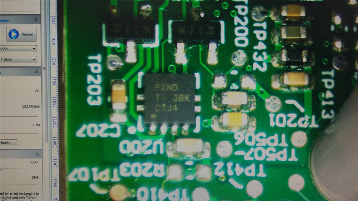
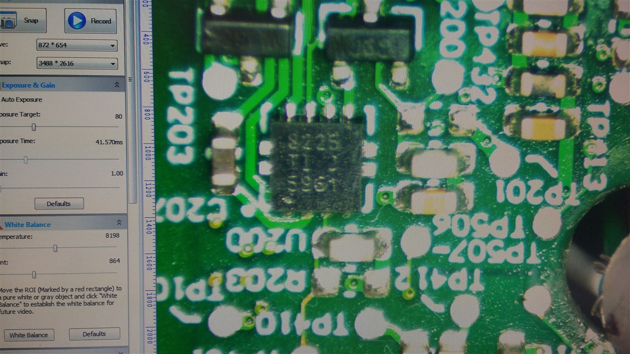
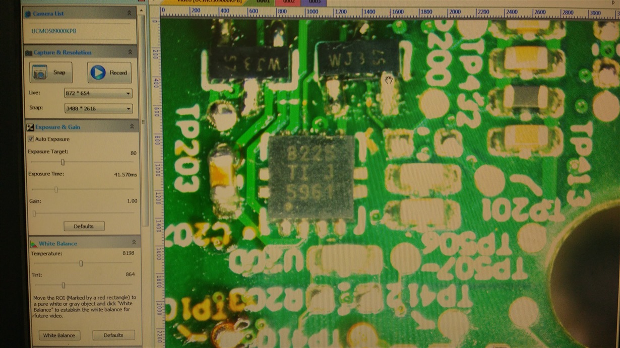
To my surprise, I also found some strange marking on the QFN parts (marking should be PXND but it's something else).

1) Could you confirm these parts are genuine?
2) Is there an issue with leaving a part always on?

Thanks!

  • Thanks for your interest in TI here. I've contacted the appropriate product group. You should hear from them soon.
  • Hi Leandro,

    1)

    It is difficult for us to determine if the parts are genuine from the picture. The best way to verify the authenticity of TI parts is to be sure to purchase from a TI authorized distributor, more details can also be found at this thread https://e2e.ti.com/group/helpcentral/f/301/t/113197. Note that issues can arise from using genuine parts that have been mis-handled by a non-authorized distributor (also mentioned in that article).

    Looking at the three images, the first line:

    Image 1 shows PXND which corresponds to the SON package for TPS28225-Q1 (the automotive qualified version)

    Image 2 and 3 show 8225 which corresponds to the SON package for TPS28225 (non -Q1 which is the not automotive qualified version)

    Does your application intend to use the automotive qualified version?

    2)

    There should not be any issue with keeping the enable signal high during operation. Are you using the enable signal to also monitor the VDD supply? Can you verify that:

    • The VDD supply is good during the reported lockout (EN pin can be monitored for this)
    • The bootstrap cap is given enough time to charge to provide the high side signal
    • The PWM input is not being set to the 3-state input mode unintentionally

    Can you provide more details about the conditions you are applying to the device so I can try and replicate?

    Regards,

    Will Toth

  • Hi Will,

    Thanks for your prompt reply.
    Definitely, I should be using the automotive part, I'm tracing where the non-automotive parts came from.

    To give you a little bit of context, these units are connected to constant power 24x7 and it was when we modified the firmware so it stopped turning on/off (enable) the driver that the problem showed up. Our test shows that this issue appears once or twice a day and once the unit is power cycled it gets fixed. Maybe latch-up?
    I probed the driving signals and the 125KHz/3.3V/50% duty cycle PWM driving the going into the PWM pin is stable (no jitter) and it's rise/fall time is around 19 ns.
    On the EN/PG pin I have a steady 3.3V high signal.

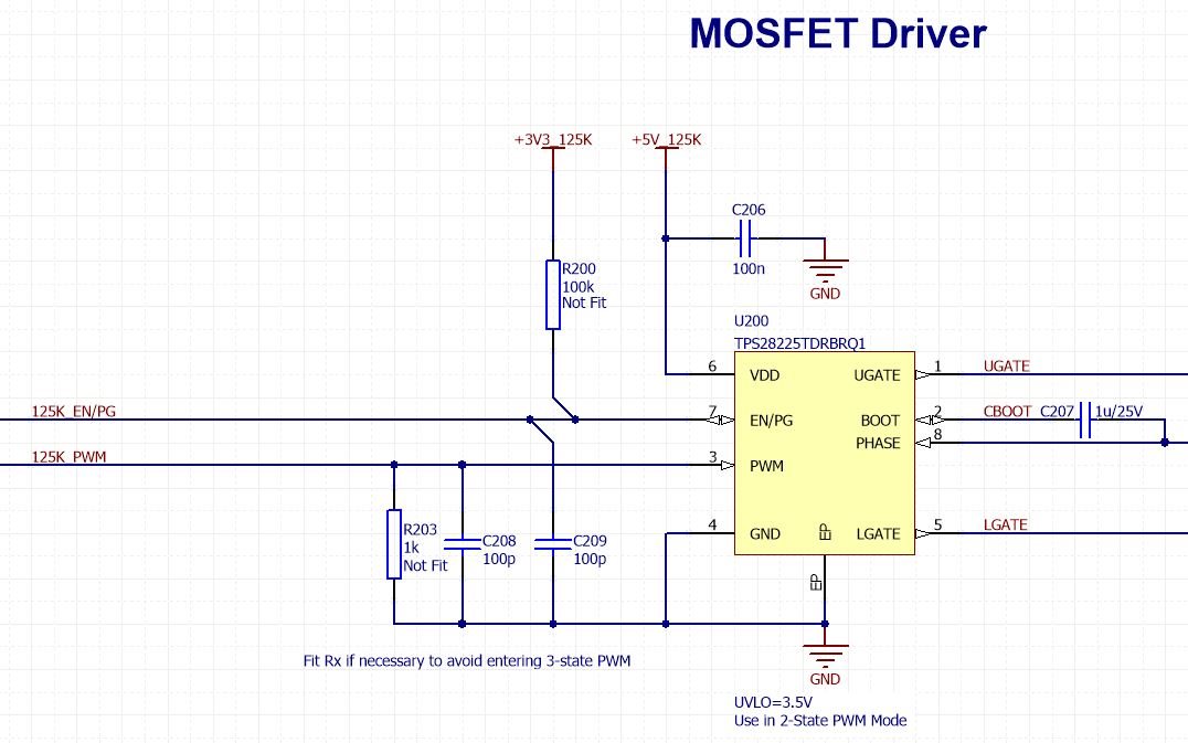
    Find below the schematic.
    R200 and R203 are not fitted. We are not using the PG indication on the host processor. The PWM signal, as I mentioned above is constantly driving the pin high and low. If it entered the 3-state mode, it should exit in the next 2 oscillations.
    I also tried applying local heating to the part and couldn't make it fail.


    Thanks!

  • Hi Leandro,

    Thanks for proving the schematic, I don't see anything obvious from it, and I have few more follow up questions on this.

    • Does the issue happen on all devices after you changed the firmware?
    • Can you try 'hard' disabling the 3-state PWM input by populating R203?
    • Is it possible to capture any waveform showing the behavior (this may be difficult due to the time scale for when you see the driver becoming stuck)
    • Is there anything else that changed when you changed the firmware? These device switch very fast, and if the board layout has too much parasitic inductance then it is possible that ringing or other effects could get to the device causing shutdown. Maybe the switching frequency/duty cycle etc. 
    • Does toggling the EN pin clear the fault, or only a power cycle?
    • Do you allow the boot cap to power up before turning on the HS? (Easy way is to hold off the PWM after EN is set high)

    Can we verify that the device does not come under the conditions that would cause the device to shutdown the driver:

    • 3-state PWM mode activated
    • UVLO detected or boot cap not able to provide VGS voltage on UGATE
    • Thermal Shutdown 
    • EN pin set low 

    Regards,

    Will Toth

  • Hi Leandro,

    Were you able to debug this any further or resolve this issue?

    Regards,
    Will Toth
  • Hi Will,

    Thanks for following up on this. I'm still trying to get it to fail, but can't reproduce the failure in the lab.

    Thanks

  • Hi Leandro,

    Maybe we can try another approach:

    First take some scope captures of the device when first powered up and in the application condition (call this 'steady state 1')

    Second, let the device sit for 30 minutes or an hour, then take the same scope captures (call this 'steady state 2')

    From that, compare to see if anything is changing, or if the device is truly in steady state.

    My thinking here is that something is changing to cause the failure behavior, so the device is not in a steady state condition at the time of failure. Maybe in that setup, even if we don't see the failure, we can see some kind of unexpected change that could lead to the shutdown behavior (or bring it close).

    Hopefully that can help, let us know if you are able to find anything.

    Regards,

    Will Toth